Legend Pro™ System User Manual Version 7
Proprietary Information of Pollogen a company of Lumenis 6
Post Treatment Care ................................................................................................................................. 54
Treatment Protocol and Conclusion .......................................................................................................... 54
13. MAINTENANCE ...................................................................................................................................... 55
13.1 Cleaning the System .......................................................................................................................... 55
13.2 Cleaning the Applicators ................................................................................................................... 55
14. FUSE REPLACEMENT ............................................................................................................................. 55
15. Troubleshooting .................................................................................................................................... 56
16. WARRANTY TERMS ............................................................................................................................... 58
17. ELECTROMAGNETIC COMPATIBILITY TABLE SHOWN IN SECTION 5.2.2 IEC 60601-1-2 Ed. 4.0 (2014) 59
18. DIAGRAM FOR THE RF OUTPUT THAT SHOW THE SUBJECT DEVICE POWER OUTPUT VS. OUTPUT
CONTROL ........................................................................................................................................................... 60
19. DIAGRAM FOR POWER OUTPUT AT FULL AND HALF FOR THE LOAD RANGE OF 25 - 1,000Ω ............. 60
Figures:
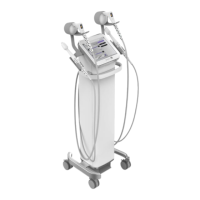
Figure 1: Legend Pro™ Main System Components (Left – front view, Right – back view) ............... 13
Figure 2: User Interface – Control panel ............................................................................................ 14
Figure 3:Back Panel ............................................................................................................................ 15
Figure 4: VO applicator ...................................................................................................................... 15
Figure 5:gen36 tip ............................................................................................................................... 16
Figure 6:gen12 tip ............................................................................................................................... 16
Figure 7: gen36L tip............................................................................................................................ 16
Figure 8: gen100 tip ............................................................................................................................ 16
Figure 9: H7X7 tip .............................................................................................................................. 16
Figure 10: Applicator No.1 ................................................................................................................. 17
Figure 11: Applicator No.2 ................................................................................................................. 17
Figure 12: Applicator No. 3 ................................................................................................................ 18
Figure 13: Foot Switch........................................................................................................................ 18
Figure 14 : Patient controlled manual switch ..................................................................................... 18
Figure 15: Non-Contact Infrared Thermometer .................................................................................. 19
Figure 16: Unpacking the System ....................................................................................................... 28
Tables:
Table 1: Precautionary Symbols and Definitions ................................................................................. 7
Table 2: Technical Specifications ....................................................................................................... 19
Table 3: Symbols used throughout this User Manual ......................................................................... 21
Table 4: Labels affixed to the System and disposables ...................................................................... 27
Table 5: Treatment Parameters for TriPollar® ................................................................................... 52
Table 6: Typical treatment parameters for face treatment .................................................................. 52