EasyManuals Logo

Power Electronics SD300 Series User Manual

Power Electronics SD300 Series
354 pages
To Next Page IconTo Next Page
To Previous Page IconTo Previous Page
Page #183 background imageLoading...
Page #183 background image
POWER ELECTRONICS
DESCRIPTION OF PROGRAMMING PARAMETERS
181
Screen
Description
Default
value
Range
Function
Set on
RUN
OU.57
Relay FDT
level
30.00Hz
0.00 to
dr.20
Value of the output frequency for digital
outputs FDT options.
YES
OU.58
Relay FDT
band
10.00Hz
0.00 to
dr.20
Detection frequency band for digital outputs
FDT options.
YES
OU.61
Pulse output
mode
Frequen
cy
0 to 15
Pulse output setting.
OPT.
FUNCTION
OPT.
FUNCTION
0
Frequency
8
TargetFq
1
O/pCurr
9
RampFreq
2
O/pVolt
10
SpeedFdb
3
DCLinkV
12
PIDRefVal
4
Torque
13
PIDFdbVal
5
O/pPower
14
PIDO/p
6
Idse
15
Constant
7
Iqse
YES
OU.62
Pulse output
gain
100.0%
-1000.0
to
1000.0%
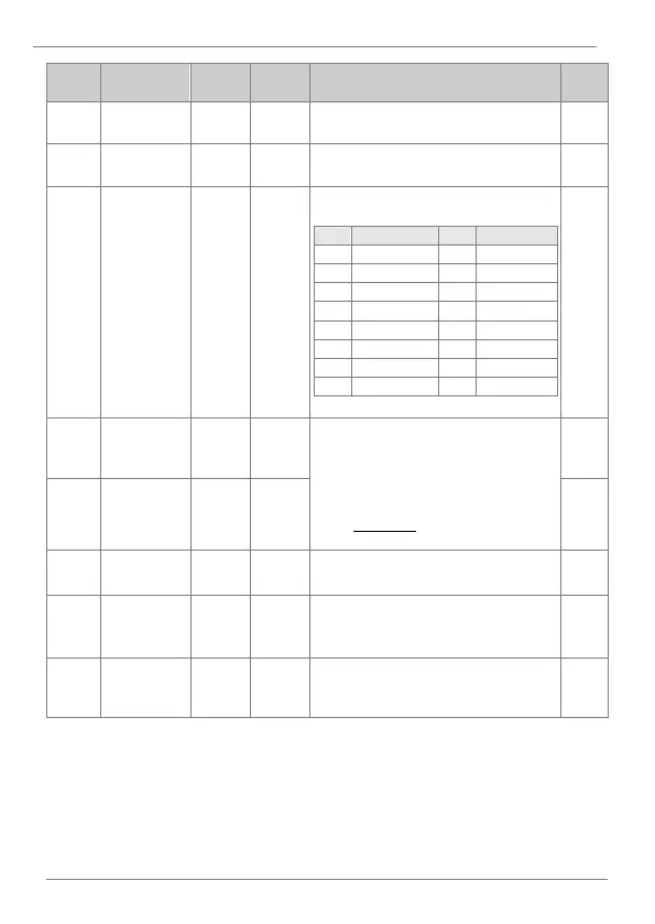
Adjusts output value and offset. If
frequency is selected as an output, it will
operate according to the following
equation:
𝑇0 =
𝐹𝑟𝑒𝑞𝑢𝑒𝑛𝑐𝑦
𝑀𝑎𝑥𝐹𝑟𝑒𝑞
× 𝑇𝑂 𝑔𝑎𝑖𝑛 × 𝑇𝑂 𝐵𝑖𝑎𝑠
YES
OU.63
Pulse output
offset
0.0%
-100.0 to
100.0%
YES
OU.64
Pulse output
filter
5ms
0 to
10000ms
Sets filter time constant on analog output.
YES
OU.65
Pulse output
constant
setting
0.0%
0.0 to
100.0%
If analog output item is set to constant, the
analog pulse output is dependent on the
set parameter values.
YES
OU.66
Pulse output
monitor
0.0%
0.0 to
1000.0%
Monitors analog output value. Displays the
maximum output pulse (32kHz) as a
percentage (%) of the standard.
YES

Table of Contents

Questions and Answers:

Question and Answer IconNeed help?

Do you have a question about the Power Electronics SD300 Series and is the answer not in the manual?

Power Electronics SD300 Series Specifications

General IconGeneral
BrandPower Electronics
ModelSD300 Series
CategoryInverter
LanguageEnglish

Related product manuals