Home
Power Electronics
Inverter
SD300 Series
Page 208
Power Electronics SD300 Series - Page 208
354 pages
Manual
Save Page as PDF
To Next Page
To Next Page
To Previous Page
To Previous Page
Loading...
SD300
POWER ELECTRONICS
206
DESCRIPTION OF PROGRAMMING PARAMETERS
Screen
Description
Default
value
Range
Function
Set on
RUN
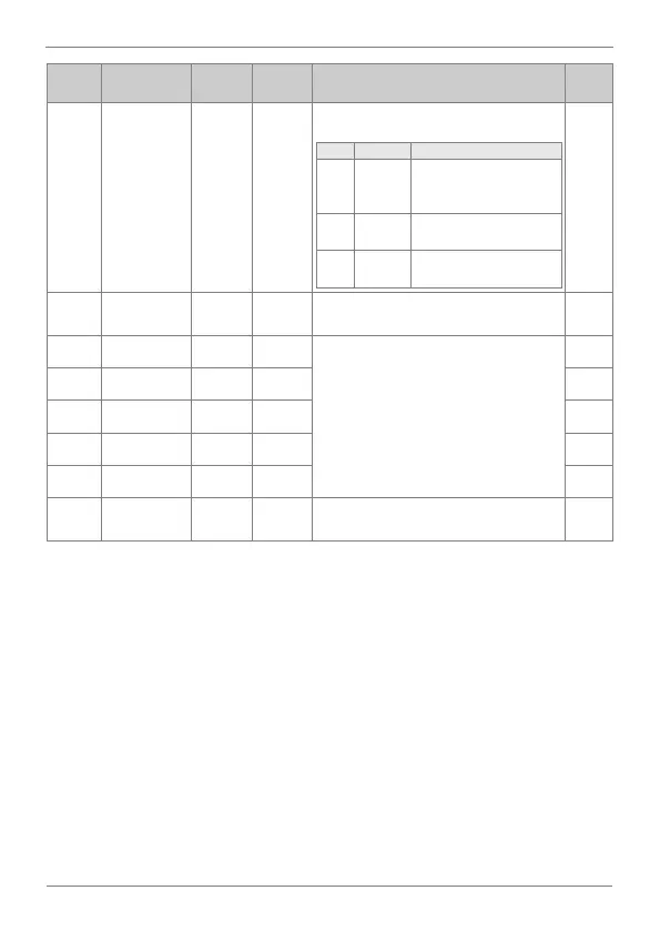
Pr.89
CAP fan
status
0
00 to 11
Shows the status of ca
pacitor fans.
OPT.
DESCR.
FUNCTION
00
None
There
are
no
w
arnings
neither
in
the
capacitors
nor in fans.
01
CAP
warning
There
is
a
warning
in
the
capacitor.
10
FAN
warning
There
is
a
warning
in
the
fan.
YES
Pr.90
Warning
information
-
-
Warning information.
-
Pr.91
Fifth fault
nOn
-
It
st
ores
in
formation
on
the
types
of
faults,
the
frequency,
t
he
current
a
nd
the
acceleration/deceleration
conditi
on
at
t
he
time of
fault. The latest fault is automatically
stored in the ‘Pr.95
➔
First fault’.
-
Pr.92
Fourth fault
nOn
-
-
Pr.93
Third fault
nOn
-
-
Pr.94
Second fault
nOn
-
-
Pr.95
First fault
nOn
-
-
Pr.96
Reset fault
history
0
0-1
It
allows
cle
aring
the
f
ault
history
s
tored
from ‘Pr.91’ to ‘Pr.95’.
YES
207
209
Table of Contents
Main Page
About this Manual
4
Table of Contents
6
Safety Symbols
9
Safety Instructions
10
1 Introduction
16
2 Configuration Table & Standard Ratings
17
Configuration Table
17
Standard Ratings - 230VAC Single-Phase
18
Standard Ratings - 230VAC 3-Phase
18
Standard Ratings - 400VAC
19
3 Technical Characteristics
21
Enhanced Sensorless Control
24
4 Dimensions
26
IP20 Drives Dimensions
26
IP66 Drives Dimensions
37
5 Reception, Handling and Transportation
42
Reception and Storage
42
Handling and Transportation
42
6 Mechanical Installation
44
Environmental Ratings
44
Drive Mounting
45
Clearances
46
Cooling
48
7 Power Connections
51
Basic Configuration
51
Topology
52
Power Terminals
53
Power Connection and Wiring
60
Ground Connection
64
EMC Installation Requirements
65
Protections
70
Dynamic Braking Resistors
72
8 Control Connection
74
Wiring Recommendations
74
Control Cables Access
75
Control Board Terminals Description
76
Control Switches
82
STO - Safe Torque off
82
9 Commissioning
84
10 Maintenance
87
Cooling
87
Warnings
88
Routine Inspection
88
11 Use of the Display
92
12 Status Messages
96
List of Status Messages
96
13 Warning & Fault Messages
97
List of Warning Messages
97
List of Fault Messages & Troubleshooting
99
14 Description of Programming Parameters
106
Group 0: Operation
106
Group 1: Drive → Dr
107
Group 2: Basic Functions → Ba
118
Group 3: Expanded Functions → Ad
130
Group 4: Control Functions → Cn
143
Group 5: Inputs → in
160
Group 6: Outputs → OU
175
Group 7: Communication Bus → CM
184
Group 8: PID → AP
190
Group 9: Protections → Pr
197
Group 10: Second Motor → M2
209
Group 11: PLC Sequence → US
212
Group 12: PLC Function → UF
214
15 Modbus Communication
221
Introduction
221
Supported Modbus Function Codes
225
Addressing Modes
228
Summary of Modbus Addresses
229
16 Accessories
276
Communications
277
Extension I/O
277
Conduit Kit
278
Flange Type
279
17 Commonly Used Configurations
292
Start/Stop Command and Speed Setting from Keyboard
292
Start/Stop Command by Keyboard and Speed Setting by Analogue Input
294
Start/Stop Command by Terminals and Speed Setting by Analogue Input
297
Multi-Speed Commands (Multi-Step Frequencies) Using P5, P6 and P7
300
Constant Pressure Control and Automatic Stop at Zero Level Flow
303
Speed Control (Up/Down Potentiometer) and Start/Stop Commands by Terminals
306
Permanent Magnet Synchronous Motor Control
309
18 Configuration Register
318
Declaration of Conformity Ce
351
Related product manuals
Power Electronics SD700
101 pages
Power Electronics SD700 Series
105 pages