EasyManuals Logo

Power Electronics SD300 Series User Manual

Power Electronics SD300 Series
354 pages
To Next Page IconTo Next Page
To Previous Page IconTo Previous Page
Page #81 background imageLoading...
Page #81 background image
POWER ELECTRONICS
CONTROL CONNECTION
79
Pulse Output Signals Connection in IP66 Drives
In IP66 drives, the pulse output signal is shared with the Q1 terminal. This
terminal must be set as TO in the parameter G6.33 and the next
connections must be performed to use it as a train pulse output:
Connect a 1/4W, 560Ω resistor between VR and Q1
terminals.
Connect EG and CM terminals.
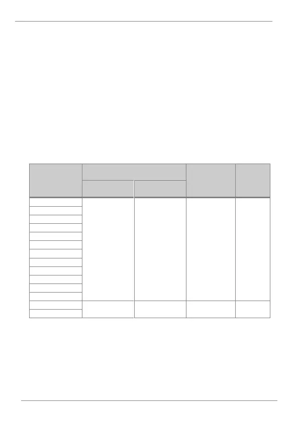
Recommended Cable Section
The recommended wire characteristics are summarized in the table below.
The wire length of the safety input should not exceed 30m.
Terminal Type
Recommended wire size [mm
2
]
(AWG)
Screw
Torque
[N.m]
No crimp-style
terminal
Crimp-style
terminal
P1 P7, CM
0.75 (18)
0.5 (20)
M2 (1/32“)
0.22 ~ 0.25
VR
V1
I2
AO
Q1
EG
24
TI
TO
SA, SB, SC
S+, S-, SG
A1, B1, C1
1.0 (17)
1.5 (15)
M2.6 (3/32“)
0.4
A2, C2

Table of Contents

Questions and Answers:

Question and Answer IconNeed help?

Do you have a question about the Power Electronics SD300 Series and is the answer not in the manual?

Power Electronics SD300 Series Specifications

General IconGeneral
BrandPower Electronics
ModelSD300 Series
CategoryInverter
LanguageEnglish

Related product manuals