PowerFleet
®
VAC4 and VAC4S Hardware User’s Guide
27-Impact Cal Error (Refer to Hardware Guide) [SHUTDOWN] Impact sensor test failed during sensor calibration.
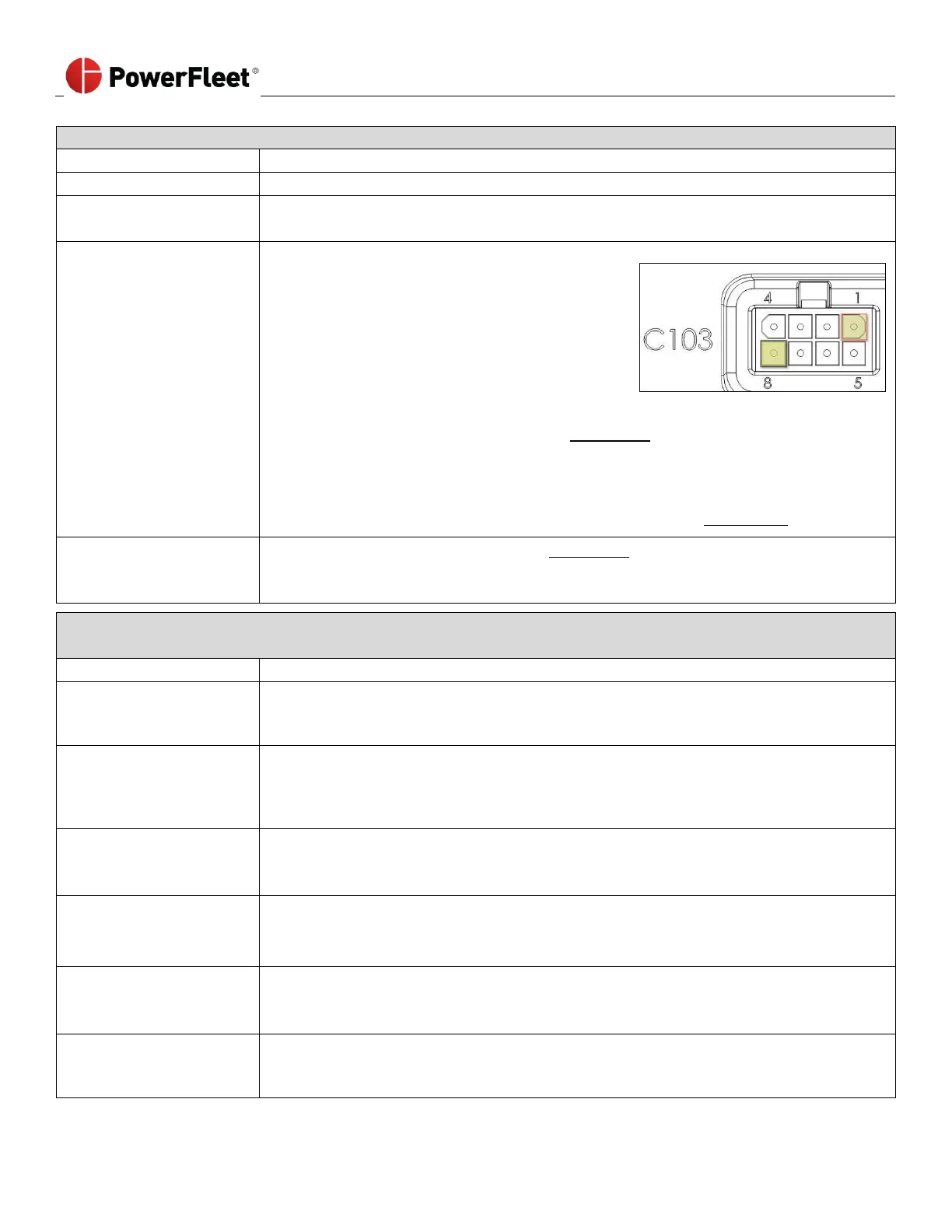
Verify that the impact sensor is properly connected to the VAC (connector C103).
Impact sensor cable
damage
• Verify that the impact sensor cable is not damaged.
• Replace sensor as needed and retest.
Impact sensor is not
getting power from the
VAC
• Verify that the VAC is supplying adequate
voltage by unplugging the impact sensor
connector and connecting a voltmeter to pin
1 (positive) and pin 8 (negative) on C103 of
the VAC. The image at right shows how to
read the pin layout and direction.
• You must have 5.5 ± 0.5 volts DC.
• If the VAC is not supplying 5.5 ± 0.5 VDC
o Complete an RMA Request form (See Appendix A)
o Call PowerFleet’s Customer Service for an RMA number.
o Only the VAC should be returned for analysis/repair.
o Once VAC is removed, system MUST be hard-bypassed to use vehicle.
• Follow instructions on how to hard-bypass the system. (See Appendix B)
• Complete an RMA Request form (See Appendix A)
• Call PowerFleet’s Customer Service for an RMA number.
• Only the Impact sensor should be returned for analysis/ repair.
28-FWD Motion Error (Refer to Hardware Guide) [SHUTDOWN] The VAC did not correctly detect forward motion
during the configuration wizard phase when asked to move the vehicle forward for three second.
Speeding during drive
forward test
• Log in to the VAC as a Maintenance operator and re-run the configuration wizard
(see Section 2).
• Drive slowly where directed
Insufficient “BLU” (motion
sensing) connection point
• Verify that the “BLU” wire is connected to the proper traction (motion) sensing circuit.
Refer to the PowerFleet
®
Installation Guide.
• Log in to the VAC as a Maintenance operator and re-run the configuration wizard
(see Section 2)
Failed fuse on “BLU”
(motion sensing) wire
• Verify that the fuse for the “BLU” wire is not blown or missing.
• Repair as needed.
• Log in to VAC as a Maintenance operator and re-run the configuration wizard (see Section 2)
“BRN” wire connection
point (Internal
combustion vehicles only)
• Verify that the “BRN” wire is connected to the proper traction (motion) sensing circuit. Refer
to the PowerFleet
®
Installation Guide.
• Log in to VAC as a Maintenance operator and re-run the configuration wizard (see Section 2)
Incorrect forward motion
values
• Log in to VAC as a Maintenance operator and re-run the configuration wizard (see Section 2).
• Log in to the VAC and review the motion values (see: “Defining ‘Motion’ Manually”).
• Adjust values as needed.
• Use an ohmmeter to check resistance to verify cable integrity (an “open” or zero reading
indicates a damaged cable) on the “BLU” wire.
• Replace the cables as needed and retest.