PowerFleet
®
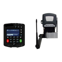
VAC4 and VAC4S Hardware User’s Guide
29-RVS Motion Error (Refer to Hardware Guide)
[SHUTDOWN] The VAC did not correctly detect reverse motion during the configuration wizard phase when asked to
move the vehicle in reverse for three second.
Speeding during drive
forward test
• Log in to the VAC as a Maintenance operator and re-run the configuration wizard
(see Section 2).
• Drive slowly where directed.
Insufficient “BLU”
(motion sensing)
connection point
• Verify that the “BLU” wire is connected to the proper traction (motion) sensing circuit.
Refer to the PowerFleet
®
Installation Guide.
• Log in to the VAC as a Maintenance operator and re-run the configuration wizard
(see Section 2)
Failed fuse on “BLU”
(motion sensing) wire
• Verify that the fuse for the “BLU” wire is not blown or missing.
• Repair as needed.
• Log in to the VAC as a Maintenance operator and re-run the configuration wizard
(see Section 2).
“BRN” wire connection
point (Internal
combustion vehicles
only)
• Verify that the “BRN” wire is connected to the proper traction (motion) sensing circuit.
Refer to the PowerFleet
®
Installation Guide.
• Log in to the VAC as a Maintenance operator and re-run the configuration wizard
(see Section 2)
Incorrect reverse motion
values
• Log in to the VAC as a Maintenance operator and re-run the configuration wizard
(see Section 2).
• Log in to the VAC and review the motion values (see: “Defining ‘Motion’ Manually”).
• Adjust values as needed.
• Use an ohmmeter to check resistance to verify cable integrity (an “open” or zero
reading indicates a damaged cable) on the “BLU” wire.
• Replace the cable as needed and retest.
Vehicle has separate
forward and reverse
motors
• Use a dual-diode solution to split the “BLU” wire into 2 wires to sense when either of
the separate drive motors are active.