PowerFleet
®
VAC4 and VAC4S Hardware User’s Guide
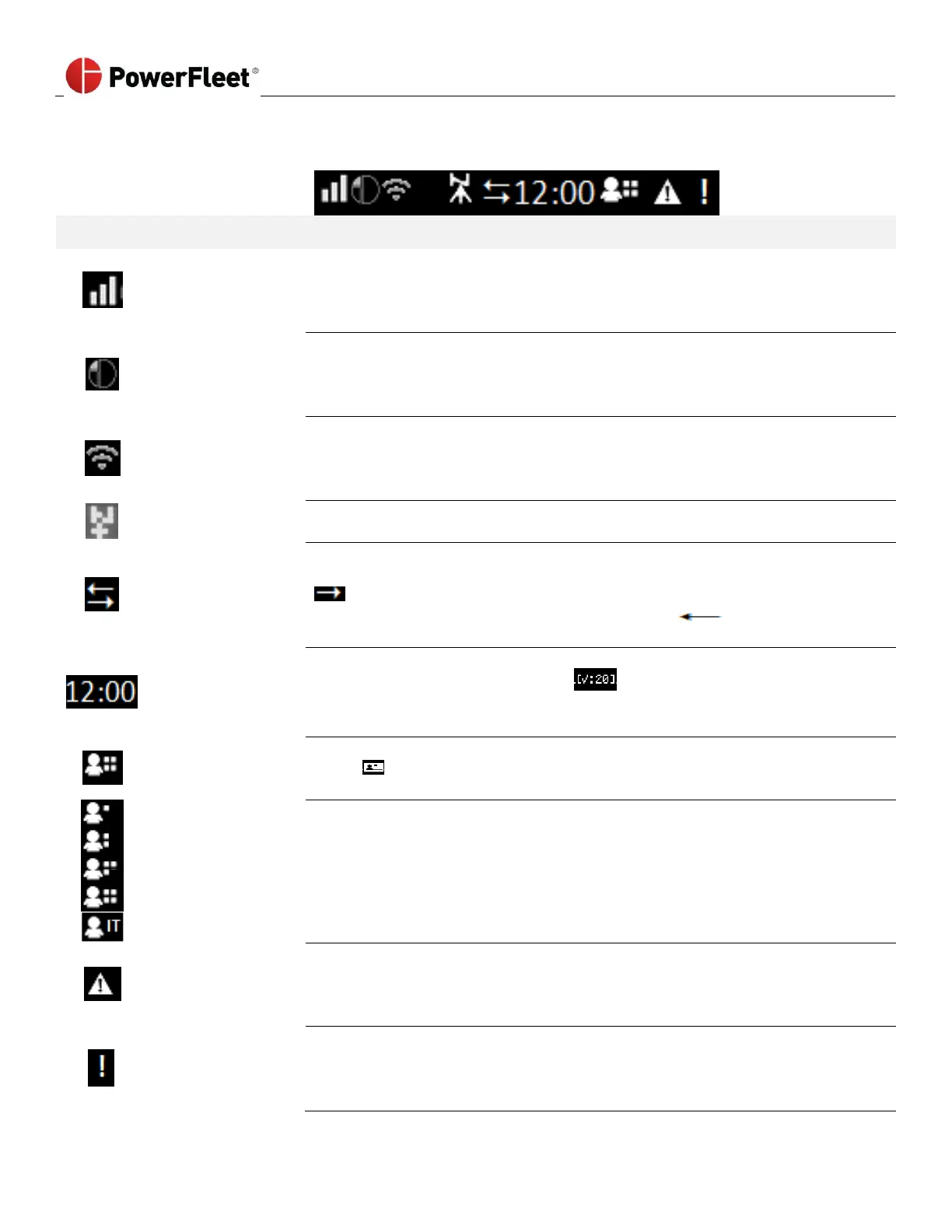
The VAC screen displays the current time, text, status icons (top row) and menu options.
Some icons are described as follows:
Reception bars provide an indication of signal strength the VAC is currently
experiencing for the wireless communication method which is affected by the
proximity to nearby WAMs or AP’s.
(X without bars = no coverage, 1 bar = weakest, 3 bars = strongest)
IRF communication icon indicates that the VAC is ready to use or is using
Intelligent RF (IRF) to communicate with the system. If inverted, the VAC has data
to send to a WAM but is unable to do so using IRF. IRF is a proprietary 868/915
MHz technology. Refer to reception bars to determine communication strength.
Wi-Fi communication icon indicates that the VAC is ready to use or is using Wi-Fi
to communicate with the server. If inverted, the VAC has data to send to the
server but is unable to do so using Wi-Fi. Refer to the reception bars to determine
the strength of the communication.
GPS triangulation icon indicates that the VAC has triangulated its location with
GPS satellites. Direction is found through this navigational aid.
OEM CAN communication icon indicates that the VAC is configured to
communicate with a CAN equipped vehicle. If only the arrow pointed to the right
is visible, the VAC has not recently received data from the CAN (such as when
the key is off). If only the arrow pointed to the left is visible,
communication with the CAN is failing.
The time clock (bracketed) indicates the current local time (24-hour clock format).
The time is replaced by a countdown when a safety checklist has to be
completed. If the time is blank [--:--], the VAC does not yet know the local time
zone such as when it is first installed and yet to communicate to the system.
Logged-in Operator
Authorization Level
Logged-in operator authorization level indicators are inverted icons (black on
white) when the operator is not recognized in the system software (i.e. new
IDs in “Any ID” mode)
The Standard operator logged in.
The Master operator logged in.
The Maintenance operator logged in.
The Administrator logged in (IDSY personnel only).
An IT operator logged in.
The Diagnostic Error icon is accompanied by a flashing red LED on top of the VAC.
At least one REFERENCE or FUNCTIONAL diagnostic error (i.e. Impact sensor
error) is active on the vehicle. However, these errors Do Not lock the vehicle or
prevent operator use of the VAC.
Diagnostic
Error
(Lockout)
The Diagnostic Error icon is accompanied by a flashing red LED on top of the VAC.
The vehicle is Locked Out for all operators except Maintenance users. At least one
SAFETY/ SHUTDOWN diagnostic error (i.e. Vehicle not correctly configured for
motion) is active on the vehicle and there is a driver safety risk.