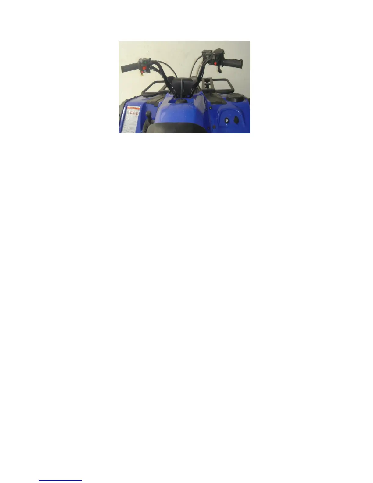
Figure 4-1-12
2. Altitude balance on each end of the steering bar
must be less than 3mm, otherwise replace the
steering bar. Figure 4-1-12
3. Check if there exists any slip thread, crack or other
defects on the fastening bolts, in which case the
bolts must be replaced.
4. Check whether the steering bar clip is damaged
(Figure 4-1-12). (Radial run out and wear condition
of the inner surface must be less than 0.8mm)
Otherwise, replace the steering bar clip.
4.1.2.3 Assembly of the steering bar
1. Connect the steering bar, clip and holder with the
main frame by hexagon flange bolts M8*30 (4pcs) and
adjust the direction of brake cables on both left and
right handlebar and clutch cable (Figure 4-1-2)


 To Next Page