Safety Features and Equipment 7-7
PA-1628Operator's ManualH3-45 COACH
Description
System includes the following elements:
l Special tire valves;
l
RF sensor inside each tire, fixed to the valve.
Sensors provide continuous tire pressure and
temperature reading. The normal sensor
battery lifespan is 5 years. The remaining
lifespan is displayed as a percentage in the
TPMS display;
l 3 antennas to receive the sensors RF signal
(one in the front spare tire compartment, one
above the L.H. side rear wheels and one
above the R.H. side rear wheels);
l A TPMS receiver connected to the antennas
and located in the front electrical
compartment, above the CECM;
l A TPMS display built in the L.H. dashboard
panel (with On-Screen TPMS version);
l A “Tire Pressure Warning” indicator.
NOTE
It is recommended to check the remaining battery
lifespan when changing the tires in order to replace
the sensors at the same time if they are due for
replacement before the next change.
The telltale panel indicator illuminates for 3 seconds
when the ignition switch is turned ON to check the
display operation and the communication between
the display and the vehicle multiplex system. This
confirms the communication between the TPMS
display and CECM.
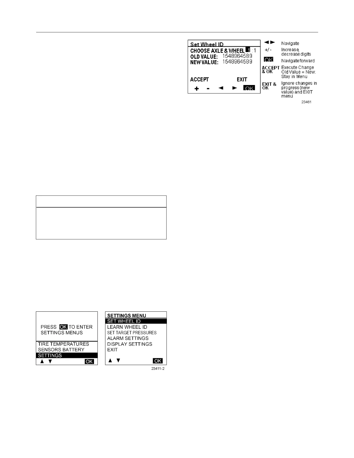
Setting The On-Screen TPMS
l Set Wheel ID
l Learn Wheel ID
This menu allows learning new wheel sensors ID.
The user can learn only one wheel, several wheels or
all wheels of the vehicle. The sequence
automatically jumps to the next wheel such that a
user can initiate all wheels without having to come
back to the display between each wheel.
The display uses a pressure change as the criteria to
recognize which wheel sensor the operator wants to
get assigned to a given location. The amount of
pressure change required is established at 2 PSI.
A pressure change of about 3 PSI is needed to wake
up a sensor and then an extra amount of pressure
change of 2 PSI is needed to trigger the display. The
operator has to create a pressure change by at least
6 PSI and then wait for the display to recognize the
pressure change. The wait time corresponds to the
sensor sampling rate.
When entering the menu, the axle 1, wheel 1 is
selected by default as a starting point for the
learning. The user can select another axle with +/- ,
move the cursor to the wheel number with the right
arrow and select another wheel with the +/- or move
the cursor down to the start learning button.
After the start learning button is selected, the display
stores the first transmission it gets from each sensor
ID into the “initial pressure” for that sensor ID. Then it
compares each subsequent pressure received for
that sensor ID with the initial one and when the
comparison shows a delta pressure exceeding the
defined level required, this sensor ID is assigned to
the selected tire location.
Once a wheel ID has been assigned, the display
increments the number of wheels done and it moves
to the next axle/wheel in the sequence, waiting for
another sensor to come up with a pressure change.
Within one learning session, the display remembers
which sensor has been assigned and it will not
assign it twice.
The sequence increments the display of the next
wheel on the same axle, counting wheels from left to








 To Next Page