Section 14: STEERING
14 X3-45 Commuter PA1593 DOB 2400-2489 Section 14 Updated Oct.2014
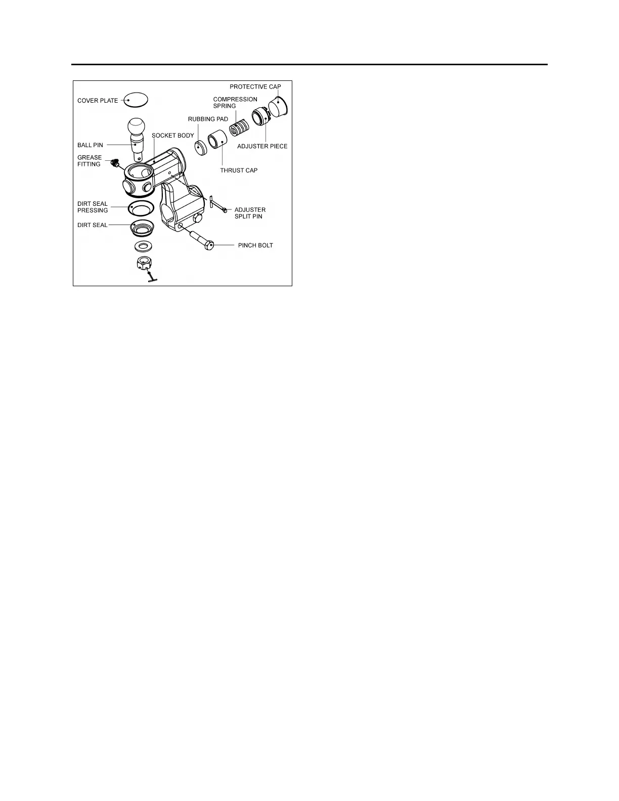
FIGURE 22: DROP TYPE BALL JOINT FOUND ON TIE
ROD (2X) AND DRAG LINK (1X)
11.6.2 Dismantling Drop Type Ball Joint
1. Remove dirt seal and dirt seal pressing from
ball pin.
2. Slacken pinch bolt nut then unscrew and
remove ball socket assembly from tie rod
having first marked ball socket body and tie
rod to enable tracking on re-assembly.
3. Remove adjuster split pin from ball socket
body.
4. Remove cap then using a suitable tool i.e.: a
piece or 1”x1/8”x 9” flat bar, unscrew and
remove adjuster piece. Waggle ball pin to
free thrust cap.
5. Remove compression spring and thrust cap
from ball socket body.
6. Relieve peening on socket body top then
using a hide faced mallet, tap ball pin out of
body. This operation will also remove cover
plate from body.
7. The rubbing pad can now be removed from
body.
Thoroughly clean all parts and check for
wear, renewing where necessary.
11.6.3 Assembling Drop Type Ball Joint
1. Apply a bead of Loctite 638 sealant to
mating corner of rubbing pad in socket body
then knock rubbing pad into its recess in ball
socket body.
2. Thoroughly grease rubbing pad and ball pin
with Shell Retinax LX or equivalent.
3. Insert ball pin into body.
4. Insert thrust cap, compression spring and
adjuster piece into body.
5. Tighten adjuster piece fully home (SOLID)
locating thrust cup onto ball pin.
6. Still with tool located on adjuster piece, back
off carefully (LEAST AMOUNT) until adjuster
piece split pin is allowed to pass through
body, and that ball pin shank can be moved
by moved of hand, then remove tool.
NOTE: If ball pin does not rotate when re-
adjusted in line with above instructions, this
suggests that ball pin has local worn flats. In this
instance ball pin, thrust cup and rubbing pad
MUST be replaced, if not FAILURE could occur
in service, i.e. ball pin not being able to move in
assembly when turning from lock to lock.
7. Fit cover plate into top of ball socket body,
re-peen using a cold chisel to secure.
8. Screw assembled ball socket onto tie rod.
Lining up marks on both body and tie rod
previously made, or retracking using manual
instructions.
9. Fit pinch bolts and nuts then tighten nuts
alternately and progressively to 65- 75 lbf-ft
(88-102 Nm.) thus securing ball joint to tie
rod.
10. Fit dirt seal (pressing) and dirt seal (rubber)
onto ball pin.
11. Locate ball socket and tie rod assembly with
lever, carefully align and fit ball pin into hole
in tie rod arm.
NOTE: Ball pin and ball pin tapers in bottom tie
rod arms must be clean, dry and free from oil
prior to assembly.
12. Fit pin washer onto ball pin.
13. Screw pin nut onto ball pin then tighten to
175 lbf-ft (237 Nm) torque.
14. Using a 2lb hammer, tap tie rod arm to
"shock' ball pin into taper hole.
15. Re-torque pin nut to 175 lbf-ft (23 7Nm).
16. Fit split pin, if slot/hole are not in line, adjust
up to next slot.
Pin nut torque 175 lbf-ft, max pin nut torque
200 lbf-ft.