Section 14: STEERING
Section 14 Updated Oct.2014 X3-45 Commuter PA1593 DOB 2400-2489 15
17. Re-charge ball socket with Shell “Retinax
LX” or equivalent grease through grease
fitting.
11.7 STRAIGHT BODY TYPE BALL JOINT
FIGURE 23: STRAIGHT BODY TYPE BALL JOINT
11.7.1 Visual Inspection
• Visually inspect for missing or damages
grease fittings and replace if required.
• Damaged sealing boot or improper sealing
requires seal replacement.
• Check ball joint connection for missing cotter
pins.
• Check for looseness in the ball/socket
assembly.
FIGURE 24: ADEQUATE CLAMPING CONDITION
For adequate clamping, the ball joint threads
must be visible the entire length of the tube slot.
If not, the drag link must be adjusted or
replaced. It is either the wrong size, or improper
adjustment was used to compensate for another
problem (e.g. bent steering arm).
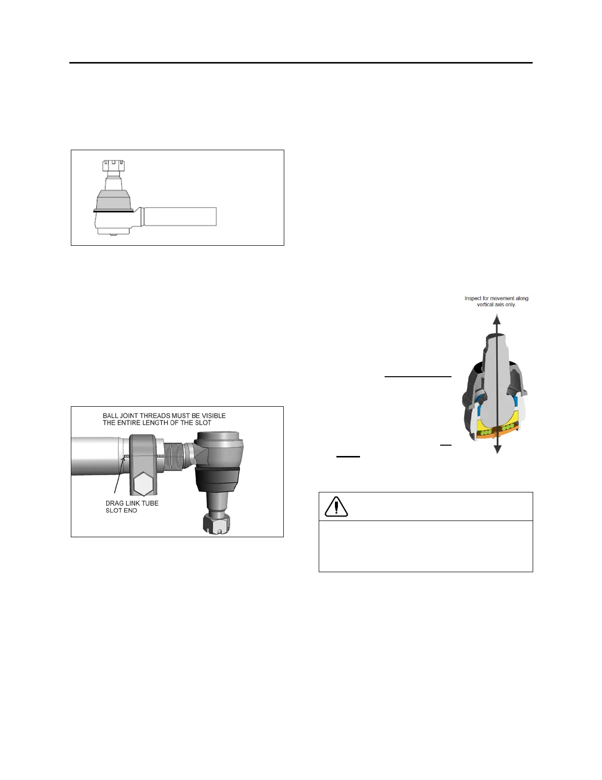
11.7.2 Straight Body Type Ball joint End Play
And Looseness
What creates movement in sockets?
In each TRW straight body type ball joints, the
compressive force of the spring creates resistive
torque by applying a constant load on the
bearing and stud.
As wear occurs on the components, the spring
creates less resistive torque. With less torque,
you no longer have the precise joint needed for
optimum steering, but you do still have a safe
linkage. When all compression is lost, it’s
time to replace the linkage. This wear can be
caused by impact, lack of lubrication and normal
wear.
1. With vehicle engine on, lightly rock the
steering wheel while checking for looseness
in any threaded joint. Observe any
looseness in the two mating tapers or any
movement of the ball pin nut. Any looseness
requires further inspection. If either of the
mating tapered parts show distortion or
wear, both parts must be replaced.
2.
wheels straight ahead and
no force is being exerted
on the linkage by the
steering gear, push and
pull the ball joint in and
out by hand
(approximately 100 lbs.
force)
in the direction of
the ball pin. If no
movement is detected,
the ball joint is safe. Any
movement detected by
hand requires
replacement of the ball
joint.
CAUTION
Do not use a wrench or other object to apply
leverage when inspecting ball joint. Applying
leverage can give distorted results and damage
components.
12. DRIVING TIPS
In order to maximize power steering pump service
life, do not attempt to turn the steering wheel
when the vehicle is stationary, and especially
when service brakes are applied (wheel locking
will oppose the effect of steering geometry which
tends to make the front wheels rotate in opposite
directions).
Persisting in turning, or maintaining the steering
wheel with an extra effort, could make the