562400-000, Issue 1.3 January 2022
Page 48 of 61
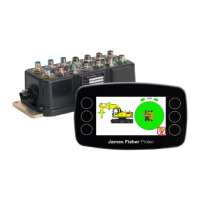
11. Test / Diagnostics
The system test function is available from the top menu screen. This feature allows the
system functions to be verified and basic troubleshooting to be performed. In this mode, the
amber LED will flash to indicate the system is in maintenance mode. The system will
continue to monitor any limits that are active. Alarm conditions and warnings will be issued
as normal.
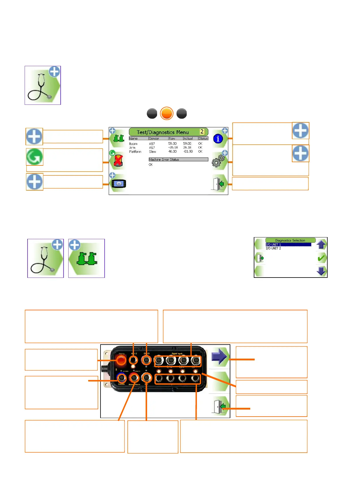
11.1. Relay Function Test
Note: Applies to PME 400 only. For PME 405 systems, see section 12.1.1 instead.
Select the I/O module unit required from the
list displayed.
To test the relays and motion cut valves use the blue arrow to highlight the appropriate output. When
highlighted no motion for that service should be possible. Input signals are indicated by LED lamp status.
Press to highlight
connection / operate
function
Amber/blue lamp. Amber LED
On denotes output is On
Link / Ign.
denotes unit failure
Motion cut outputs control hydraulic
services. See notation on screen for
individual assignment
USB port. Not
supported in
this screen
LED lamps
Exit to previous
denotes input is On
CAN S and CAN D Communication Link to
display and sensors. Amber LED denotes
output is On
Function Inputs. See notation on screen for
individual assignment. Amber LED On denotes
Display options
System
information
Beacon, Alarms
and LED test
Code protected
access to
supervisor features
Relay / LED test
Exit to previous menu
 Loading...