PLX3x Series ♦ Multi-Protocol Gateways PND Protocol
User Manual
ProSoft Technology, Inc. Page 187 of 215
January 25, 2018
Swap Read Output Data
Bytes
No Change
Word Swap
Word and
Byte Swap
Byte Swap
Specifies if and how the order of bytes in data sent is to be
rearranged. This parameter is otherwise the same as Swap
Read Input Data Bytes.
YES - Reset output database values to 0 if communications
fail.
NO - Retain output database value if communications fail.
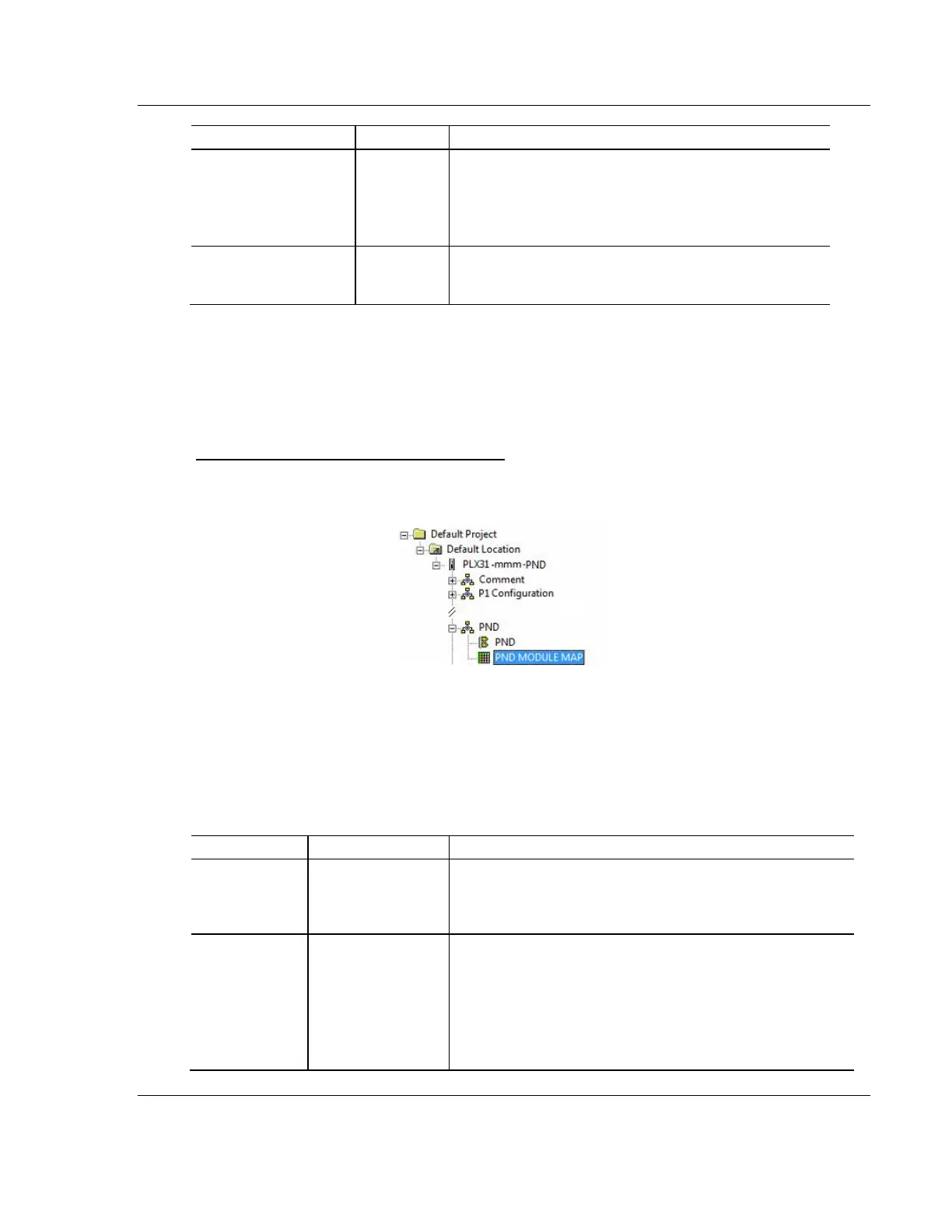
10.2.2 Configuring PND Module Map
Use the PND Module Map section in ProSoft Configuration Builder to configure
the PND Module Map parameters.
To configure the PND Module Map in PCB
1 In ProSoft Configuration Builder, click the [+] next to the gateway, then click
the [+] next to PND.
2 Double-click PND MODULE MAP to display the Edit - PND MODULE MAP
dialog box.
3 Click ADD ROW to add a new module mapping.
4 Click EDIT ROW or double-click the row to display the Edit dialog box where
you configure module mapping.
Input or Output
4, 8, 16, 32, 64, 128,
256, 512, or 1024
bytes
Specifies the module type (Input/Output) assigned to a specific
slot.
No Change
Word Swap
Word and Byte
Swap
Byte Swap
Specifies if and how the order of bytes in data received and
sent is to be rearranged. Different manufacturers store and
transmit multi-byte data in different combinations. You can use
this parameter when dealing with floating-point or other multi-
byte values, as there is no standard method of storing these
data types. You can set this parameter to rearrange the byte
order of data received or sent into an order more useful or
convenient for other applications.