PLX3x Series ♦ Multi-Protocol Gateways EIP Protocol
User Manual
ProSoft Technology, Inc. Page 85 of 215
January 25, 2018
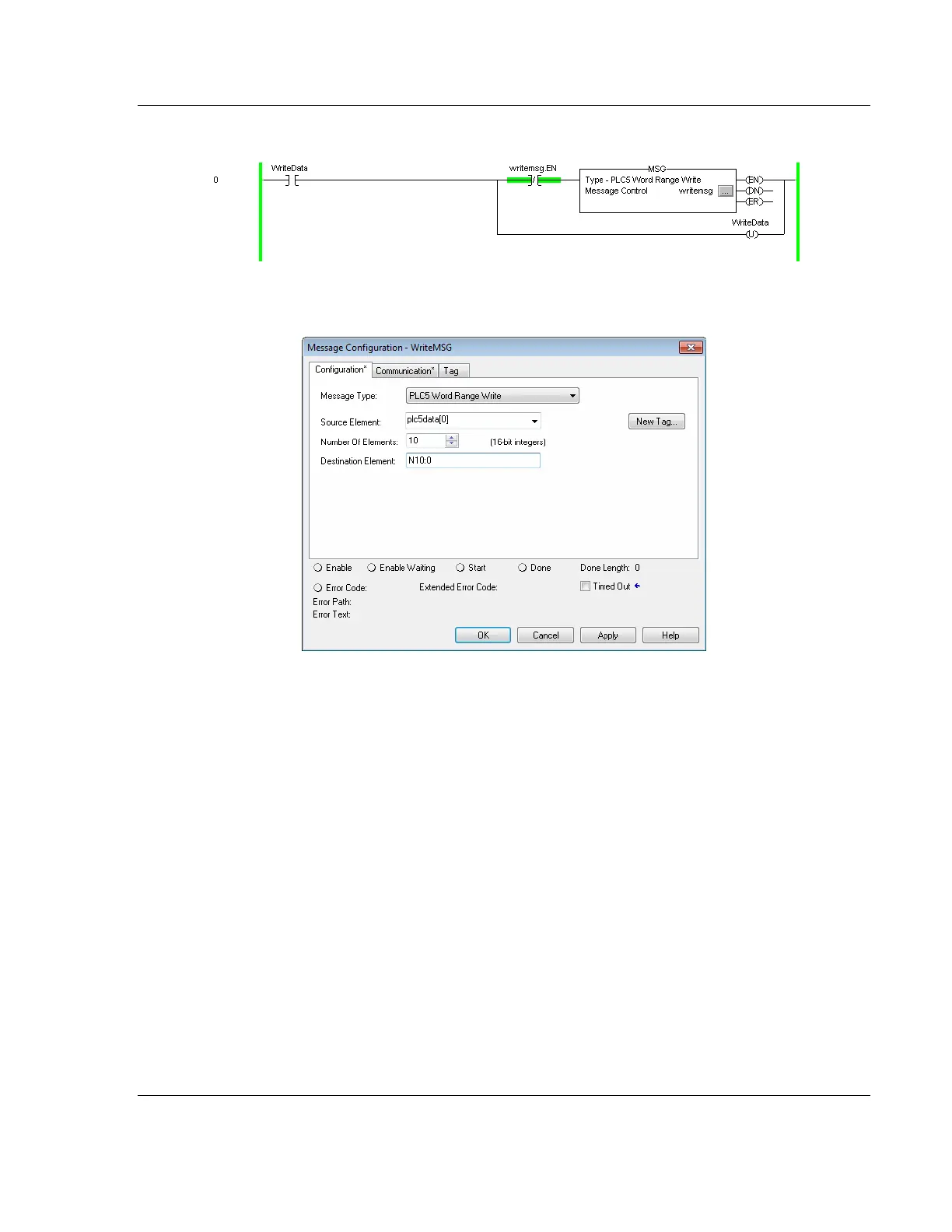
The following diagram shows an example rung that executes a write command.
1 In the Message Configuration dialog box, define the data set to be transferred
from the processor to the gateway as shown in the following image.
2 Complete the dialog box for the data area to be transferred.
o For PLC5 and SLC messages, set the DESTINATION ELEMENT to an
element in a data file (such as, N10:0).
o For the PLC2 Unprotected Write message, set the DESTINATION ELEMENT
to the address in the gateway’s internal database. This cannot be set to a
value less than ten. This is not a limitation of the gateway but of the
RSLogix software.
o For a PLC2 Unprotected Write or Read function, enter the database
address in octal format.