MVI69E-MBS ♦ CompactLogix Platform Configuring the MVI69E-MBS Using PCB
Modbus Serial Enhanced Communication Module User Manual
ProSoft Technology, Inc. Page 47 of 154
June 28, 2017
3.2 Module Configuration Parameters
3.2.1 Module Parameters
This section contains general module configuration parameters, including
database allocation and backplane transfer options.
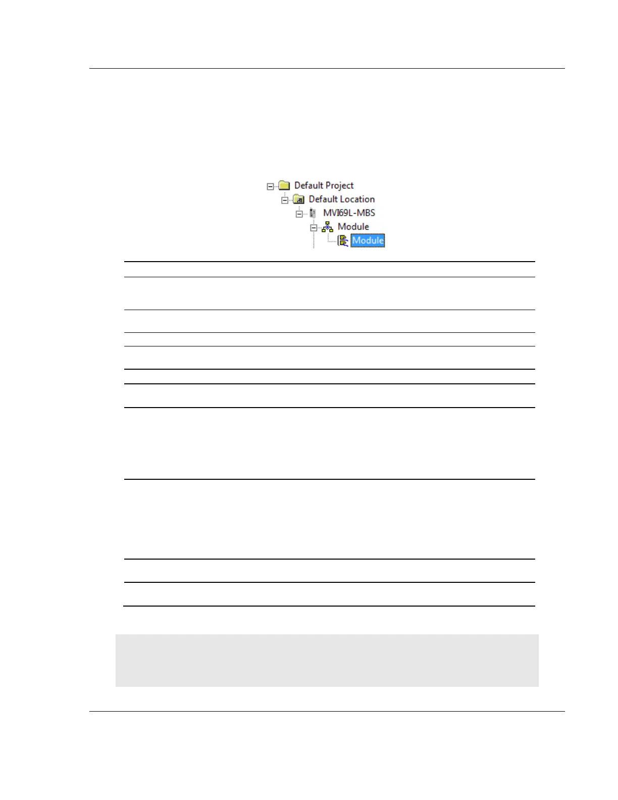
In the ProSoft Configuration Builder (PCB) tree view, double-click MODULE.
ASCII
characters
(max. 80)
Assigns a name to the module that can be viewed using the
configuration/debug port. Use this parameter to identify the module
and the configuration file.
Specifies the start of the Read Data area in module memory. Data
in this area is transferred from the module to the processor.
Specifies the size of the Read Data area.
Specifies the start of the Write Data area in module memory. Data
in this area is transferred from the processor to the module.
Specifies the size of the Write Data area.
Specifies the number of consecutive backplane transfer failures
that can occur before communications are halted.
Error/Status Block Pointer
Starting register location in the module’s database for the
error/status table. If a value of -1 is entered, the error/status data is
not placed in the database. This data must be placed in the read
data range of module memory.
This data ncludes the module version information and all server
error/status data. Refer to MBS.STATUS (page 85) for more
information.
This parameter determines if the input image data and the
module’s Read Register Data values are initialized with Read
Register Data values from the processor. If you set the parameter
to No, the Read Register Data values in the module are set to 0
upon initialization. If you set the parameter to Yes, the data is
initialized with Read Register Data values from the processor. This
option requires associated ladder logic to pass the data from the
processor to the module.
Specifies the number of words in each block transferred between
the module and processor.
Specifies the slot in the CompactLogix or MicroLogix 1500-LRP
rack for the module.
Important: The sum of the Read Register Count and Write Register Count cannot exceed 10,000
total registers. Furthermore, neither the Read Data nor the Write Data area may extend above
module register 9999. The Read Data and Write Data areas must not overlap.