MVI69E-MBS Backplane Data Exchange MVI69E-MBS ♦ CompactLogix Platform
User Manual Modbus Serial Enhanced Communication Module
Page 70 of 154 ProSoft Technology, Inc.
June 28, 2017
4.4 Data Flow Between the Module and Processor
The following topics describe the flow of data between the two pieces of
hardware (CompactLogix or MicroLogix 1500-LRP processor and MVI69E-MBS
module) and other nodes on the Modbus network. You can configure each port
on the module to emulate a Modbus Master device or a Modbus Slave device.
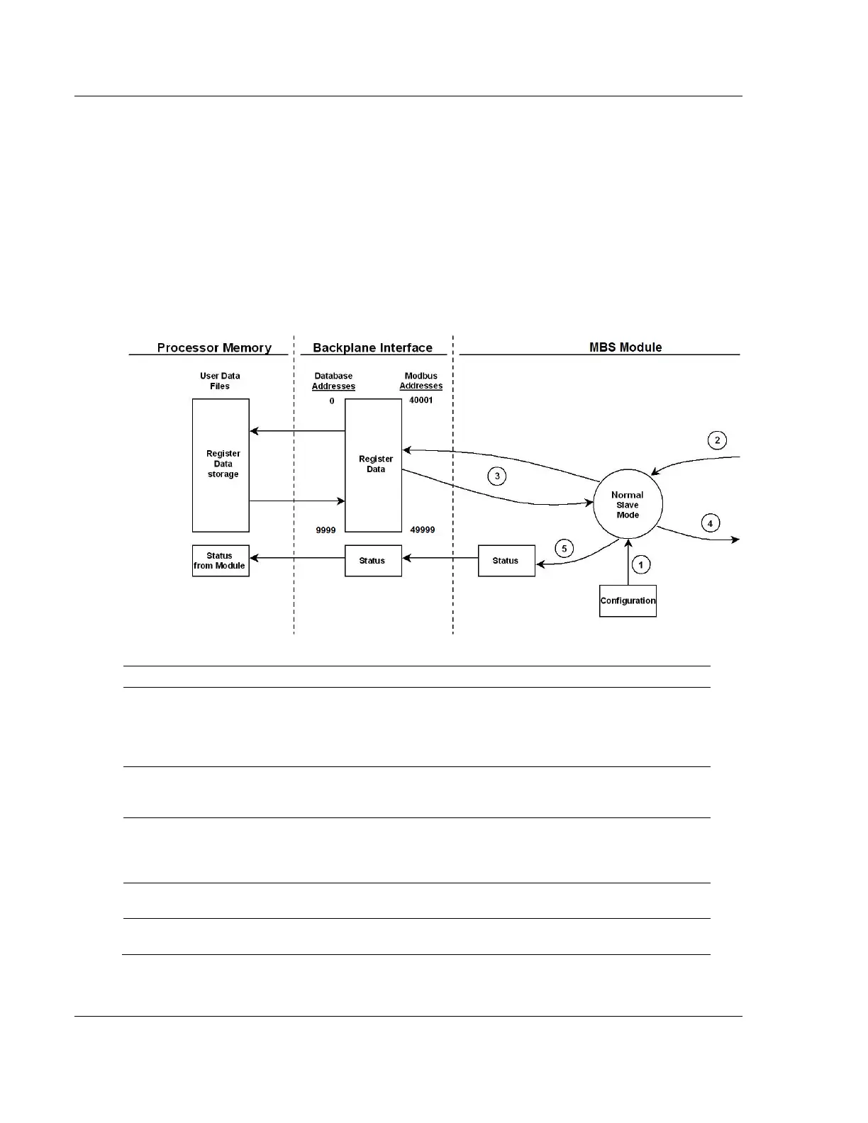
4.4.1 Slave Mode
In Slave Driver mode, the MVI69E-MBS module responds to read and write
commands issued by a master on the Modbus network. The following diagram
shows the data flow for normal Slave mode.
Any time the module restarts (boots or reboots), the Modbus slave port driver receives
configuration information from the MBS controller tags. This information configures the
serial ports and defines slave node characteristics. The configuration information may also
contain instructions to offset data stored in the database to addresses different from
addresses requested in the received messages.
A Modbus Master device, such as a Modicon PLC or an HMI application, issues a read or
write command to the module’s node address. The port driver qualifies the message before
accepting it into the module. Rejected commands cause an Exception Response.
After the module accepts the command, the data is immediately transferred to or from the
module’s internal database. On a read command, the data is read from of the database and
a response message is built. On a write command, the data is written directly into the
database and a response message is built.
After Steps 2 and 3 have been completed, either a normal response message or an
Exception Response message is sent to the Master.
Counters are available in the Status Block to permit the ladder logic program to determine
the level of activity of the Slave driver.