Configuring the MVI69E-MBS Using PCB MVI69E-MBS ♦ CompactLogix Platform
User Manual Modbus Serial Enhanced Communication Module
Page 48 of 154 ProSoft Technology, Inc.
June 28, 2017
3.2.2 Modbus Port x Parameters
This section applies to both MBS PORT 1 and MBS PORT 2.
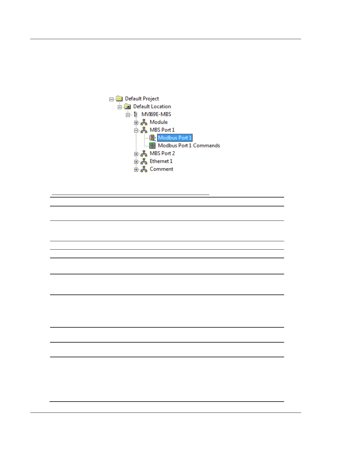
In the ProSoft Configuration Builder tree view, double-click the MODBUS PORT X
icon.
Configuration Parameters Common to Master and Slave
Specifies whether or not the port and commands are active
upon module boot-up.
Master, Slave,
or Slave with
Pass-Through
This parameter specifies which device type the port emulates.
See Slave Mode (page 70) for more information on Slave
Pass-Through options.
Specifies the Modbus protocol for the port.
Specifies the baud rate for the port.
Specifies the type of parity error checking. All devices on this
port must use the same parity setting.
Sets the number of data bits for each word used by the
protocol. All devices communicating through this port must use
the same number of data bits.
Sets the number of stop bits that signal the end of a character
in the data stream. For most applications, use one stop bit. For
slower devices that require more time to re-synchronize, use
two stop bits. All devices communicating through this port must
use the same number of stop bits.
Sets the number of milliseconds to delay after Ready To Send
(RTS) is asserted before data is transmitted.
Sets the number of milliseconds to delay after the last byte of
data is sent before the RTS modem signal is set low.
Specifies if the Clear To Send (CTS) modem control line is to
be used or not. If you set the parameter to NO, the CTS line is
not monitored. If you set the parameter to YES, the CTS line is
monitored and must be high before the module sends data.
Normally, this parameter is required when half-duplex modems
are used for communication (2-wire). This procedure is
commonly referred to as hardware handshaking.