Page 31
Pulsar Radio Telemetry System
Some Pulsar units may be fitted with an optional Radio Telemetry System.
This system cannot be retro fitted and must be purchased at the time of ordering.
The system consist of a small transmitter board or ‘Node’ that is integrated into the
SF2 housing and a receiver or ‘Gateway’ that is placed in a suitable location.
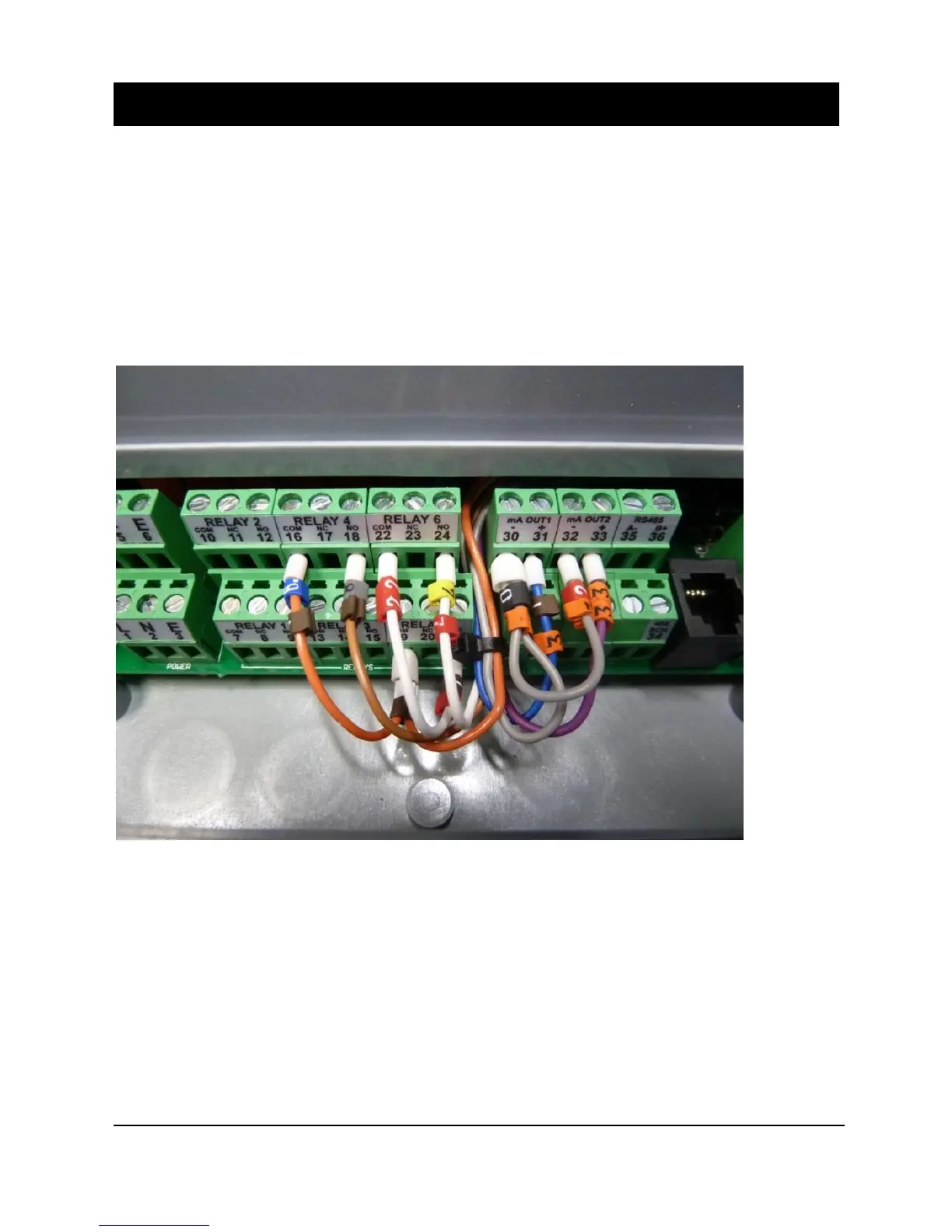
The transmitter is pre-wired into the analogue output terminals and three of the digital
outputs as shown below.
TRANSMITTER (node) WIRING
The transmitter unit has two analogue outputs and two digital outputs.
Channel 1 is mA OUT 1. Channel 2 is mA OUT 2.
Relay 4 is DIG OUT 1. Relays 5 and 6 are DIG OUT 2
The mA output will be set by the user in the Application section of the parameters to
reflect the operational 4-20 mA output span of the instrument.
The Relays should be programmed as follows.
Relay 5 should be set to be a Loss of Echo alarm, Relay 6 should be set to be a Wiper
fail. These outputs are wired in series to DIG 2 and are used to give a Failure Output.
Relay 4 can be programmed as a customer preference for Hi or Lo alarm output.
 Loading...