EB200 Manual Remote control
4052.2000.02 4.122 E-7
4.6 Device model and command processing
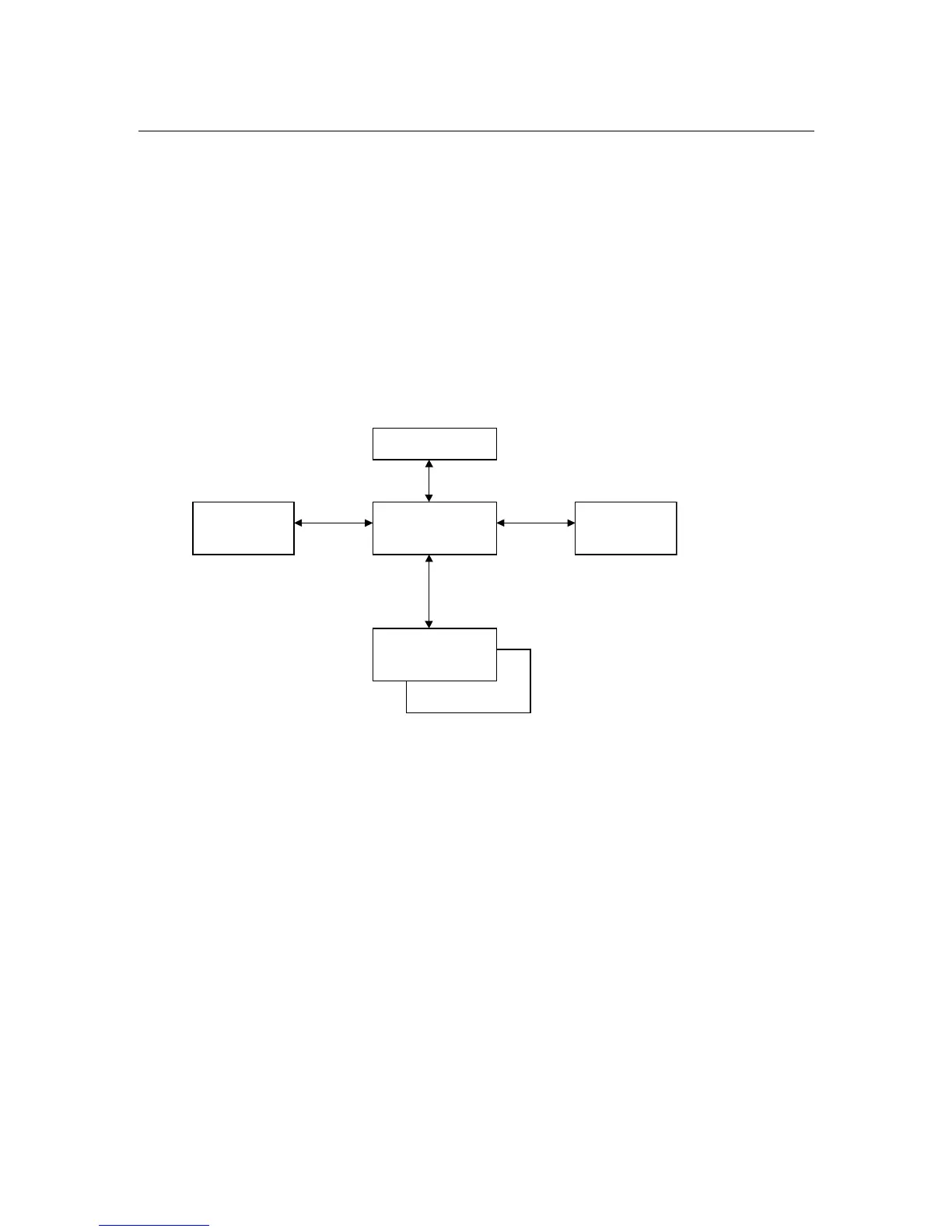
The following figure shows the basic structure of the unit under firmware aspects. The actual receiver is
isolated from the front control panel and the remote control units by a central data memory. This
memory is at the core of the EB200 firmware and deals with the following tasks:
• Administration of connected modules (receiver, front control panel, remote clients)
• Making data available to the receiver (eg receive frequency, scan parameters, etc.)
• Sequentialization of settings for simultaneous manual and remote control
• Sending messages on parameter changes to all modules.
• Storing data in the CMOS RAM for protection against power failure
Central memory
CMOS RAM
Front control
panel
Receiver
Remote client 2
Remote client 1
Fig. 4-2: Device model with remote control
As mentioned under 4.3, the unit can be controlled from the front panel and one or several remote
control units – the remote clients – simultaneously (competitive control). Upon system start, the front
control panel and the receiver are logged in to the data memory automatically. These modules are
therefore always connected. The remote clients are logged in if a host computer sets up a link to the
EB200.
The receiver obtains the required data (receive frequency, bandwidth, etc.) from the memory. It has no
data storage facility of its own and therefore has direct access to the central memory.
Due to the principle of competitive control, different clients can modify the same parameters. The
central memory sequentializes the access procedures (last client wins) and sends messages to the
other users that a parameter has been changed.