Configuration
R&S
®
TS7124M
143User Manual 1525.5394.02 ─ 05
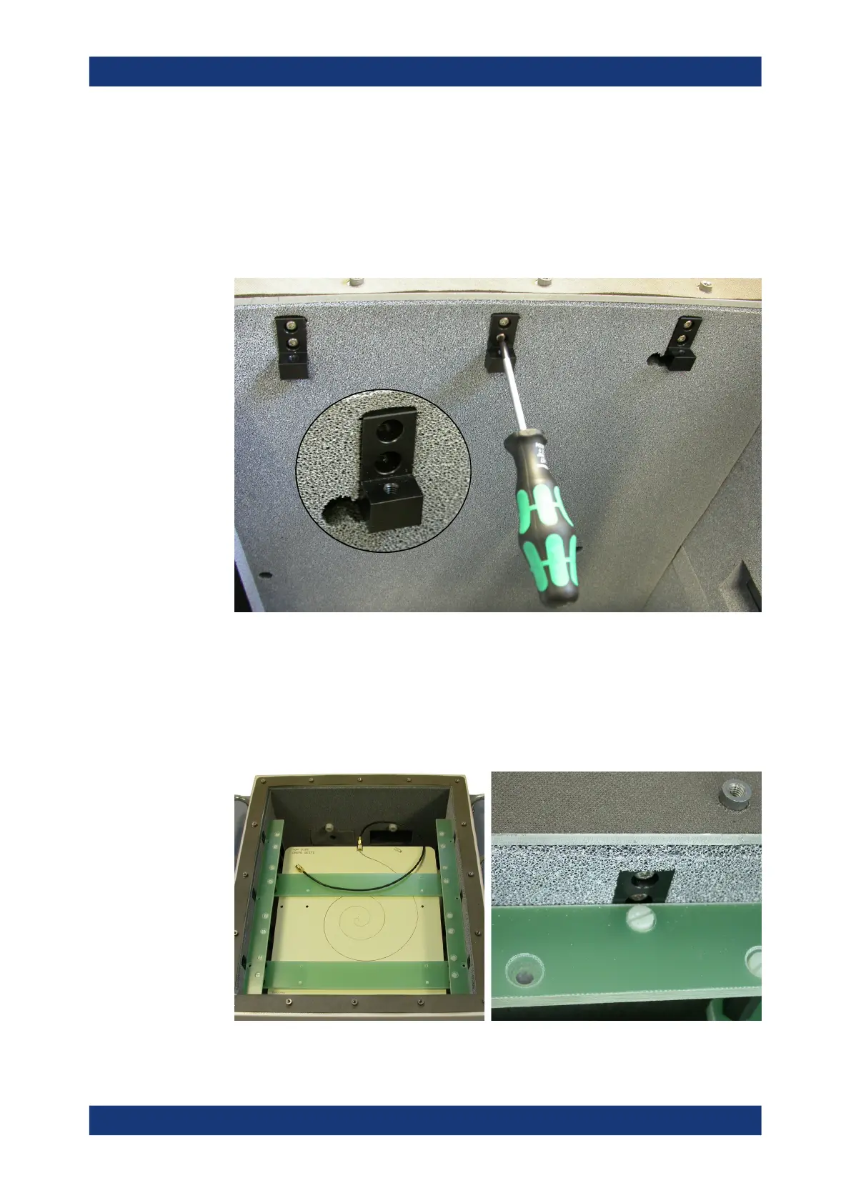
3. Inside the chamber, close to its top edge, remove the six rectangular absorber
pads (three on each side).
4. In these openings, mount the six included anodized supports for the antenna
holder. Three supports are mounted on the left side, as shown below, and the other
three supports are mounted on the right side of the chamber. Use a Torx 10 screw-
driver to tighten the twelve included screws.
5. Use a torque wrench to attach the included RF cable to the antenna's SMA con-
nector, minding the torque recommendation.
6. Place the antenna inside the chamber, with the SMA connector pointing to the rear
and the [TOP SIDE] label on the upper side.
7. Fix the antenna to the supports with the included six polymer screws (shown
below), using a flathead screwdriver.
Installing the wideband antenna