Accessories
R&S
®
TS7124M
50User Manual 1525.5394.02 ─ 05
Table 6-5: Wideband antenna specifications (*)
Parameter Value
Frequency 300 MHz to 6 GHz
VSWR (reflection coefficient) < 2 (at 300 MHz to 4 GHz)
< 2.3 (at 4 GHz to 6 GHz)
Gain -7 to 2 dBi (at 400 MHz to 3 GHz)
-15 to 0 dBi (at 3 GHz to 6 GHz)
Max. input power 27 dBm (0.5 W)
Impedance 50 Ω
Polarization circular (nom.)
Connector SMA (female)
Dimensions (W x D x H) 246 mm x 280 mm x 7 mm
(* These specifications are valid if the antenna is mounted 5 mm above an acrylic glass
sheet and a flat RF absorber that are placed on a conducting plate.)
This wideband antenna with antenna holder is not a serviceable part. If it is defective,
or if checking reveals that it is not working correctly, replace it.
See Chapter 8.3, "Checking", on page 153.
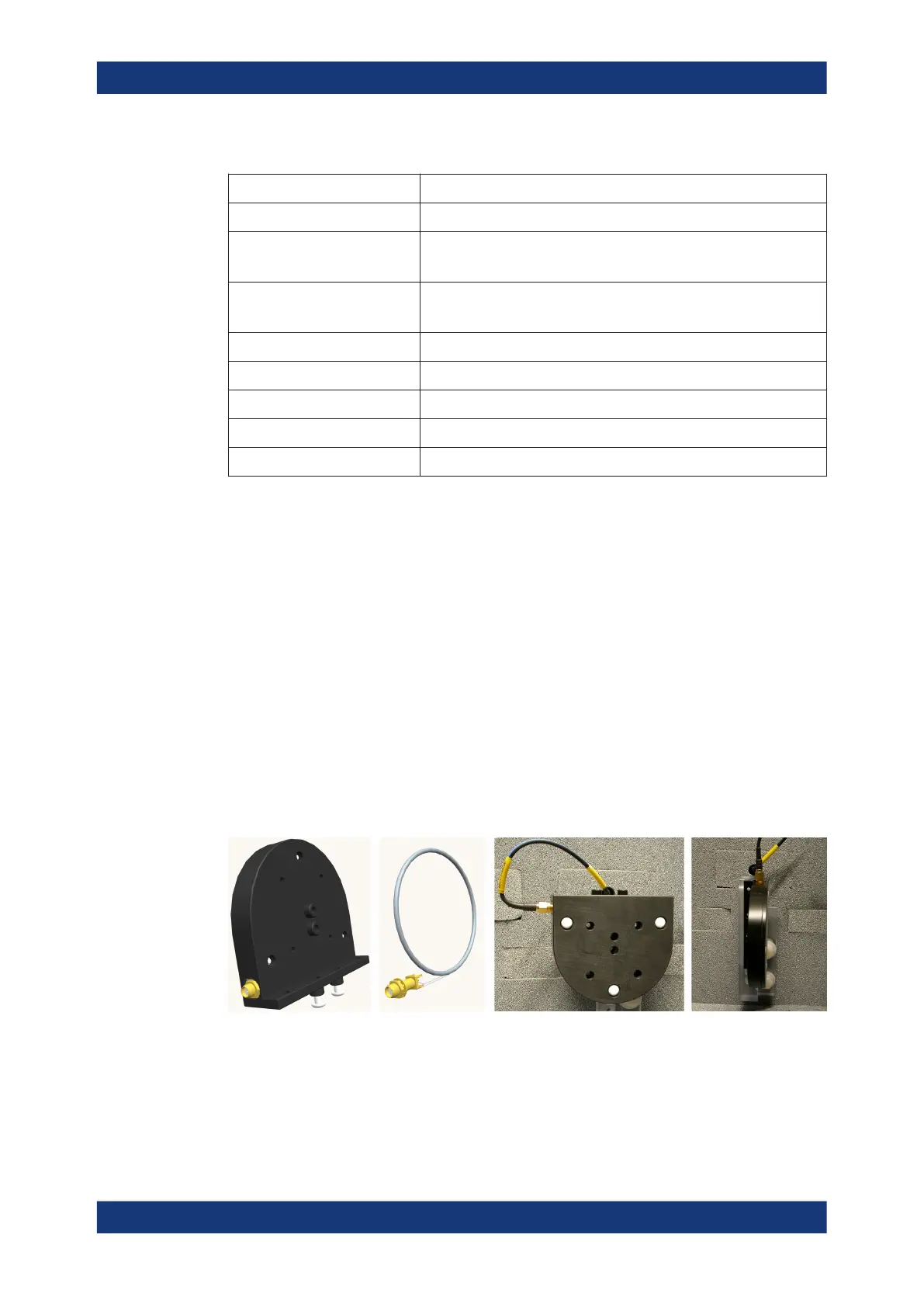
6.3.6 LF loop antenna R&S TS-F24HLF1
The low-frequency loop antenna R&S TS-F24HLF1, order no. 1530.8446.02, is used
especially for testing RFID applications that operate at a low frequency range from
20 kHz to 1 MHz.
The loop antenna is encased in a rounded housing made of POM (polyoxymethylene)
that measures approximately 80 mm x 90 mm x 14.5 mm (plus some protruding ele-
ments). A 20 cm RF cable is included in the delivery.
Figure 6-19: Two design illustrations of the antenna (left) and two typical mounting positions (right)
Antennas
 Loading...