Hardware overview
R&S
®
TS7124M
16User Manual 1525.5394.02 ─ 05
3.2 Rear tour
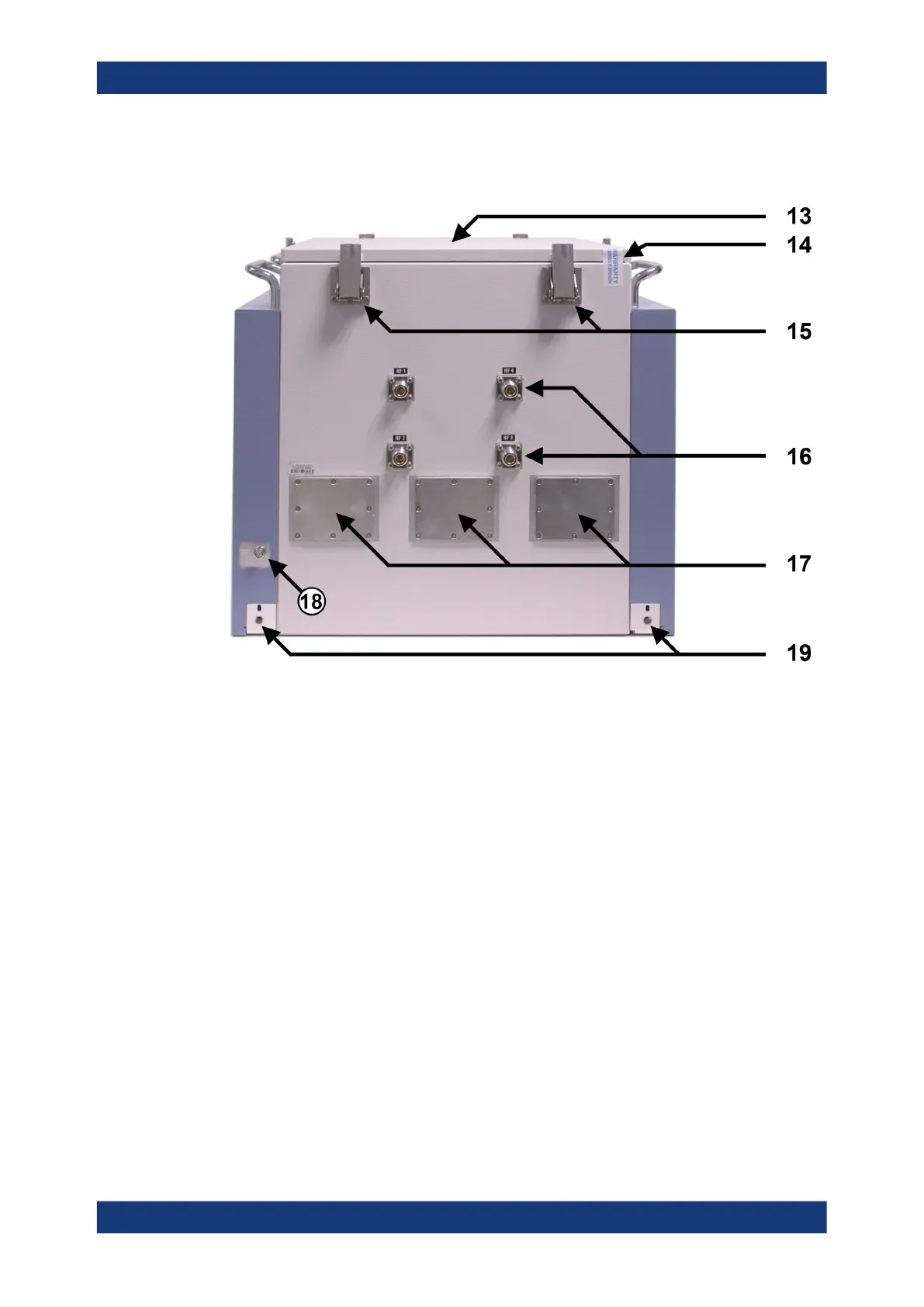
Figure 3-4: Rear side view of the RF shielded box
13 = Top cover for configuration and service issues
14 = Warranty seal of the top cover
15 = Six quick clamps of the top cover
16 = Four Rear feedthroughs for up to four antennas inside the chamber
17 = Three metal plates covering openings in the rear chamber wall for up to three optional feedthroughs,
specified in Chapter 6.6, "Feedthroughs", on page 59
18 = Earth (ground) contact
19 = Two rear screw holes for mounting brackets (included in shipment)
The top cover (13) of the RF shielded box is fixed by six quick clamps (15). It can be
removed for antenna configuration and service issues (see Chapter 7.4, "Opening and
closing the top cover", on page 77).
The warranty seal (14) indicates that the R&S TS7124M is in its original delivery state,
with a shielding effectiveness as given in the specifications document. For configura-
tion of the interior of the RF shielded box, you must open the top cover and hence
break the seal. After closing the cover it is in the user's responsibility to restore a good
shielding effectiveness. To do so, proceed as described in Chapter 7.4.3, "Adjusting
the locking force of the cover", on page 82.
At the rear side of the RF shielded box, there are four shielded RF feedthrough con-
nectors (16, see Chapter 3.2.1, "Rear feedthroughs", on page 17). These can be
used, e.g., for up to four individual antennas (see Chapter 6.3, "Antennas",
Rear tour