Accessories
R&S
®
TS7124M
34User Manual 1525.5394.02 ─ 05
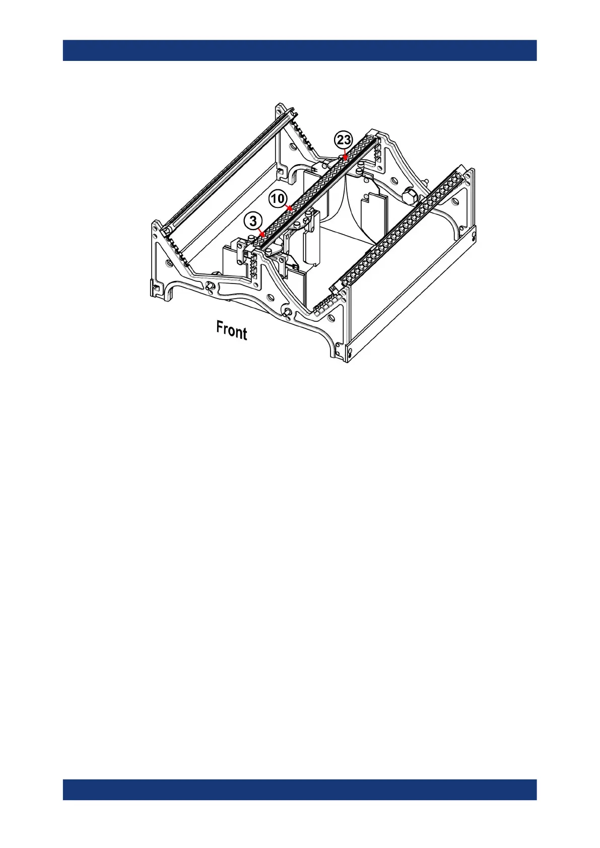
Figure 6-5: Half antenna ring with three Vivaldi antennas (V1 or V2)
3 =
Vivaldi antenna on rail 2, top, position 3 (3
rd
hole), rotation 90°
10 =
Vivaldi antenna on rail 2, top, position 10 (10
th
hole), rotation 0°
23 =
Vivaldi antenna on rail 2, top, position 23 (23
rd
hole), rotation 90°
The antennas are mounted on the center rail (rail 2), which is mounted in position 4
(top of the antenna ring). On the rail, the three antennas are mounted in positions/
holes 3, 10 and 23, as indicated in Figure 6-5. The first and the third antennas are
mounted in 90° angular position. The second (center) antenna is mounted in 0° angular
position.
Apart from the fact that the antennas are pre-installed in the antenna ring, all details
are as described in:
●
Chapter 6.2.1, "Half antenna ring R&S TS-F24-AH1", on page 31
●
Chapter 6.3.1, "Vivaldi antenna R&S TS-F24-V1", on page 40
●
Chapter 6.3.2, "Vivaldi antenna R&S TS-F24-V2", on page 42
●
Chapter 7.6, "Installing an antenna ring or holder", on page 87
●
Chapter 7.10, "Configuring Vivaldi antennas", on page 119
The half antenna ring and the antennas are no serviceable parts. If these parts are
defective or not working correctly, replace them.
6.2.3 Full antenna ring R&S TS-F24-AR
The R&S TS-F24-AR, order no. 1525.8906.02, is an optional antenna mounting struc-
ture to be placed inside the chamber. This antenna ring is called "full antenna ring" to
Antenna holders
 Loading...