Hardware overview
R&S
®
TS7124M
13User Manual 1525.5394.02 ─ 05
3 Hardware overview
This chapter describes all components of the chamber. Function and use of these com-
ponents is described in Chapter 7, "Configuration", on page 74.
Accessories for the chamber are described in Chapter 6, "Accessories", on page 30.
3.1 Front tour..................................................................................................................... 13
3.2 Rear tour...................................................................................................................... 16
3.2.1 Rear feedthroughs........................................................................................................ 17
3.1 Front tour
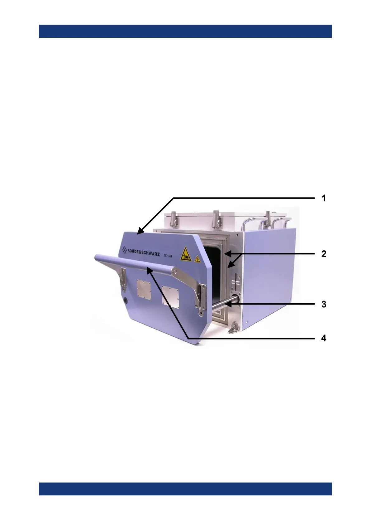
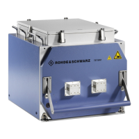
Figure 3-1: Front view of the opened RF shielded box
1 = Front door of the drawer (RF shielded box version 1525.8564.12), for DUT exchange
2 = Two grooves filled with elastic gasket for sealing the drawer's door
3 = Drawer guide rail
4 = The door's handle, here lifted up to the "open" position
The front drawer (1) of the RF shielded box is used for insertion of the DUT. The
drawer guide rails (3, one on each side) support the drawer when it is manually opened
and closed by means of the handle (4).
The polymeric gasket (2) features a conductive chromated aluminum surface to pre-
vent leakage of RF radiation out of the chamber, and into it. Avoid touching or soiling
the gasket. The front door's gasket is highly elastic for a long life over many opening
and closing cycles (see Chapter 8.2, "Maintenance intervals", on page 152).
Front tour


 To Next Page