Installation and commissioning
R&S
®
TS7124M
28User Manual 1525.5394.02 ─ 05
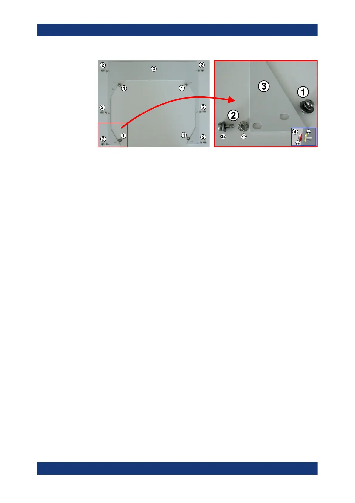
Figure 5-6: Matching the screws and washers to the various holes in the metal rack cover sheet
1 = Large washers, spring-lock washers and M6 screws (4 each) for fixing the metal sheet to the
chamber
2 = Grounding sockets, small washers and M5 screws (6 each) for fixing the metal sheet to the rack
2a = M5 screw and small washer. Insert from the front side of the metal rack cover sheet
2b = Grounding socket. Insert from the rear side of the metal rack cover sheet
3 = Metal rack cover sheet
4 = Detail: M5 screw and small washer (2a) inserted from the front side and grounding socket (2b)
inserted from the rear side of the cover sheet
9. Position the metal sheet around the chamber's door in such a way that the holes in
the sheet align with the holes in the chamber and in the rack.
10. Fix the metal rack cover sheet to the M5 cage nuts in the rack by the six screws (2)
in Figure 5-6.
11. Fix the metal rack cover sheet to the chamber, using the four screws and washers
(1) in Figure 5-6.
12. On the rear side of the rack, fix the chamber to the rails that carry the chamber.
To do so, use two of the mounting brackets shown in Figure 5-2.
13.
WARNING! Risk of injury due to heavy moving parts. Only operate the door while
the chamber is securely fixed to a stable support.
Remove the rope that secures the door from opening.
14. Ground the chamber as described in Chapter 5.4, "Grounding the RF shielded
box", on page 28.
If you remove the chamber from its location, secure the chamber's door against unin-
tentional opening during transportation and observe Chapter 4.1, "Lifting and carrying",
on page 19.
5.4 Grounding the RF shielded box
As soon as the setup of the RF shielded box is prepared according to chapters 5.2 and
5.3, ground the chamber using the electrical grounding connection as shown in Fig-
ure 5-7:
Grounding the RF shielded box
 Loading...