Configuration
R&S
®
TS7124M
76User Manual 1525.5394.02 ─ 05
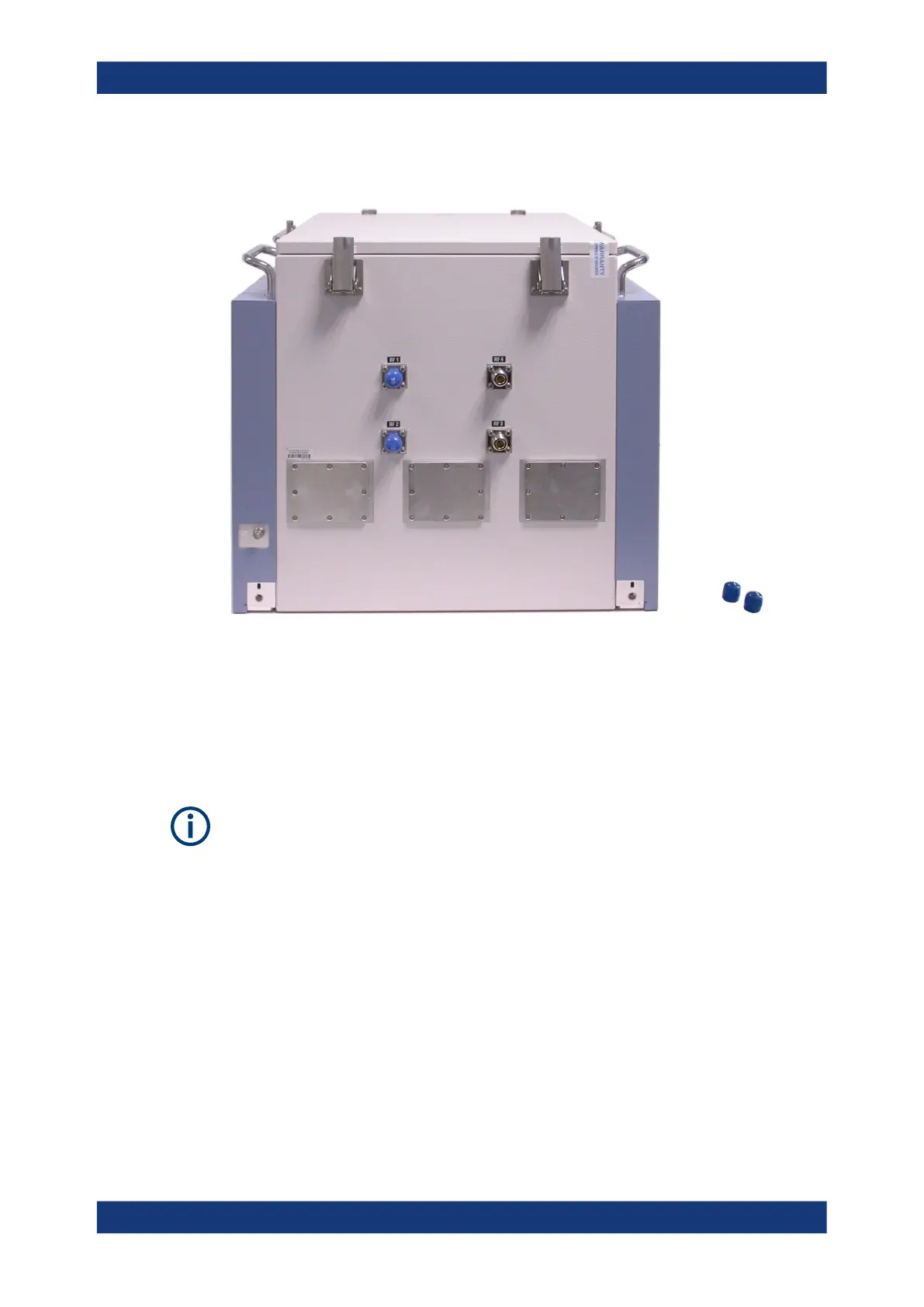
7.2 RF interfaces
Figure 7-1: N connectors with blue protective caps (left), two caps removed (right)
On the rear side of the RF shielded box, remove the protective caps from as many N
connectors as required. For more than four RF connections, install additional units of
Twin N-SMA feedthrough R&S TS-F1RFNM2.
When linking the N connectors to your test system, use shielded RF cables and a tor-
que wrench to tighten the cables' N connectors, minding the torque recommendations.
Correct positioning of the antenna connectors can be verified visually by inspecting the
connectors inside the chamber. Alternatively, a measurement of S11 parameters at all
ports may serve for verification.
7.3 Mounting a feedthrough
To install a feedthrough in the front door or in the rear-wall
1. Open the front door of the RF shielded box.
2. On the outside of the chamber, remove the eight Torx 8 screws that hold the cover
plate which has to be removed.
Mounting a feedthrough