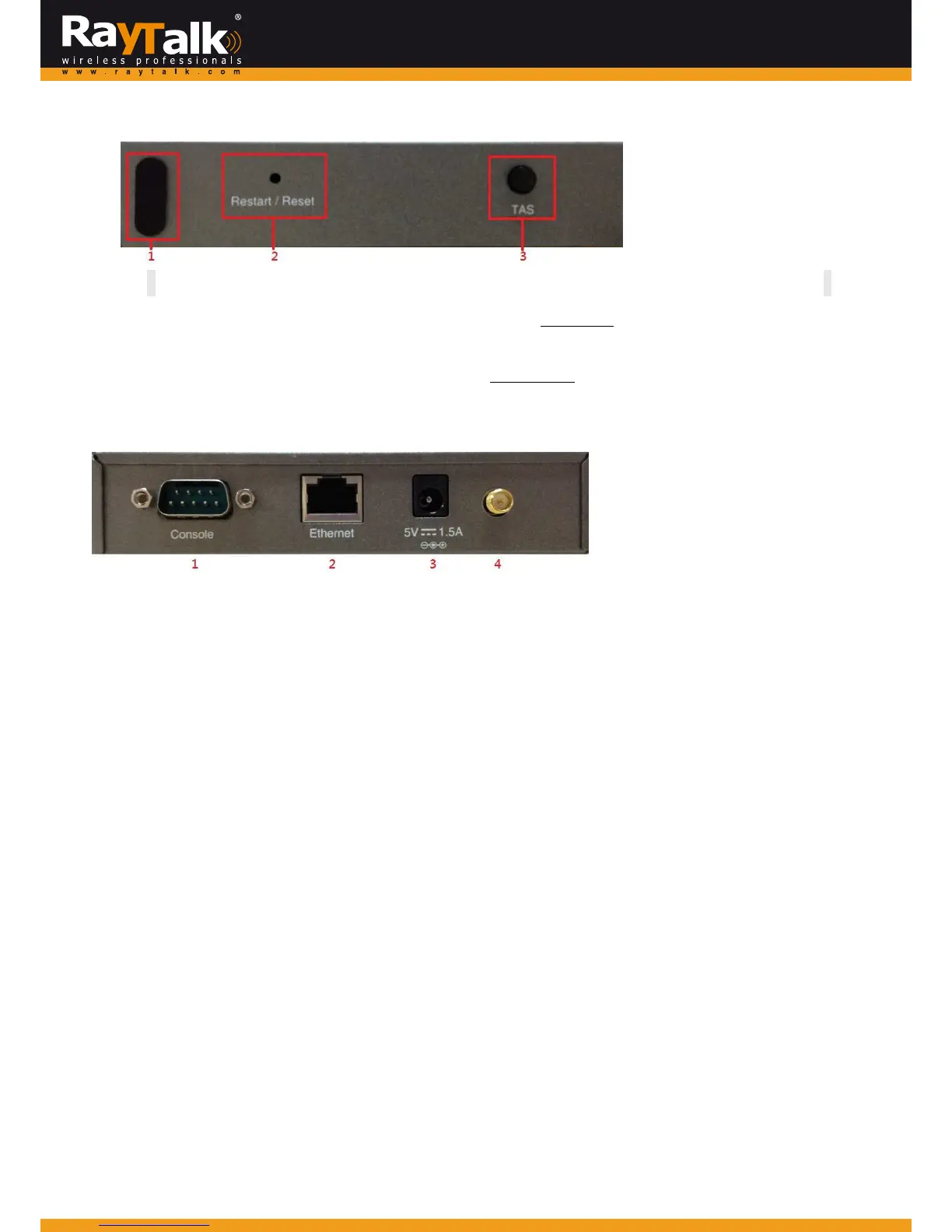
RightSidePanelOver view
RightSidePanel
1.KensingtonLock Beusedtolockthedevicetoapole.
2.Restart/Reset Poleoncetorebootthesystem.PokeforfivesecondstomakeRT‐TO696RFsetbacktofactory
defaultsettings.
3.TAS Term inalAuto Setup(TAS).Press threesecondstoinitiatetheautouplink connectionprocess.
Thiswillbeintroducedlater.
LeftSidePanel
Overview
LeftSidePanel
1.ConsoleSerialportforconnectingtoaPOSprinter.
2.EthernetRJ‐45EthernetportSerialportforconnectingtotheuplinkgatewayviawire.
3.5V/ 1.5A TheDCpowersocketforconnectingtoanexternalpowersourcethroughaDCpowersupply.
4.Antennaconnector Assemblethedi
polean
tennawithinthepackagehere.
IncludingRT‐TO696RFintoYourNetwork
1.Putrelevantdevicesinplac e.
2.AttachaRT ‐TO696RFtoapoweradaptorprovidedinthepackage.
3.AttachaPOSprintertoapoweradaptorprovidedinthepackageandturnonthepowerswitchsituatedontheleftsideofthe
device.
4.ConnectaPOSprintertotheConsoleportofRT‐TO696R FbyaRS‐232cableprovidedwithinthePOSprinterpackage.
5.Conn
ect RT‐TO696RF
to your RayTalk Interne t Subsc riber Gateways via Ethernet port or wirelessly. If you are to do it
wirelessly,conductasitesurveyinthefirstplace.
Thewirelesscoverageissubjecttochange.
6. Toverifyifthedeploymentworksfine.PressFUNC+‘1’+ENTERtoseeifRT‐TO696RFisatta
chedtoacorrectgatewayand
getanIPaddressfromit.Additionally,press‘Number ’+ENTERtoseeifanaccountwithacertainbillingplancanbeprintedout.If
itisnotworkingproperly,gotoAppendixAfortroubleshooting.



 To Next Page