3.0 CG3 User Interface
The CG3 has been designed with user-friendliness in mind. The buttons have been
labeled with descriptive icons and text to help provide an intuitive interface, which is
intended to help you get familiar with its use quickly. See figure 3 below for a brief
guide to the user interface.
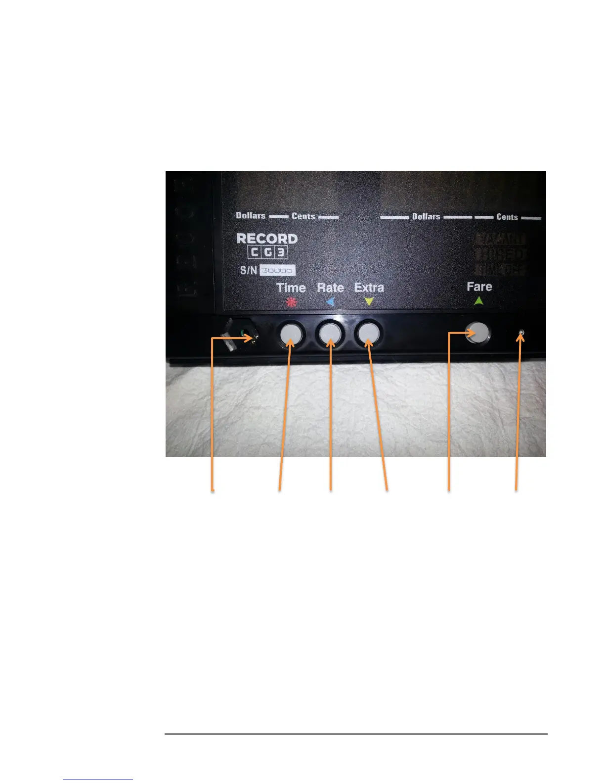
Figure 3
Config Switch Time Button Rate Button Extra Button Fare Button Light Sensor
The text above the buttons refer to the roles that the buttons play primarily while a
fare is in operation (Hired Mode), and the colored icons (arrows and star /asterisk)
refer to functions that the buttons provide in all other modes, which is mainly to select
and adjust values, and to scroll various menus.
3.1 Config Switch
The Config Switch, or hidden lock, refers to two copper-plated holes located on the
circuit-board, which are accessible through the two small, parallel holes in the
hexagonal indent (see Figure 4 below). The Config Switch is used to enter
Configuration Mode.