VT2300/VT2500 Circuit in Photo Mode:
Photo Mode
Selector
Selector 2
I II
I
I
1
1
1
VPH of Platlen/
1
Original
Background
yl
Ak
w
I
I
~AB,LABJ
--? 7-7
Q
4 bit
Image
Signal
3 J&
A/D Converter
Density: O
Density: 1
SHMRT(LOW signal when in Photo/Line mode)
(Low signal when in Photo mode)
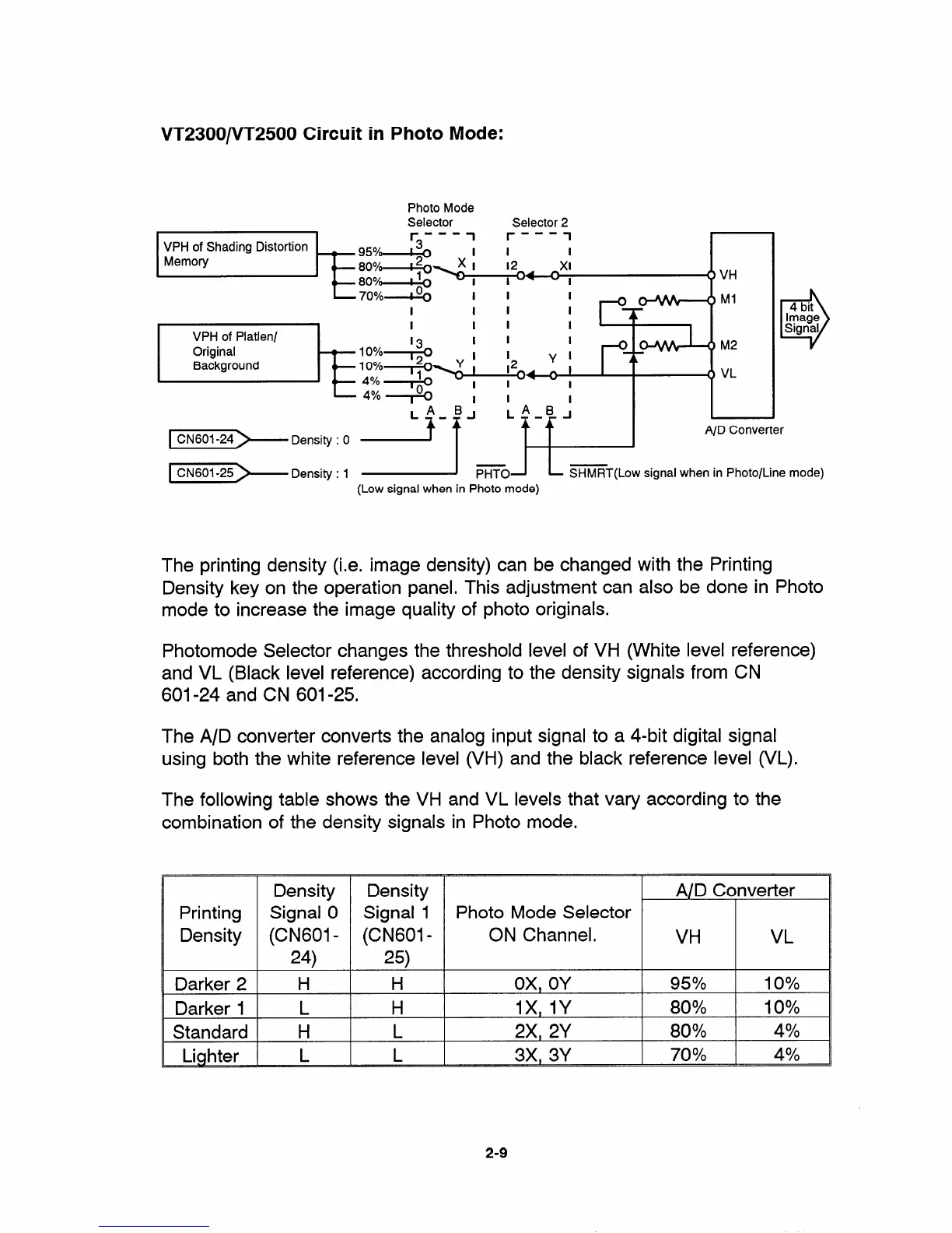
The printing density (i.e. image density) can be changed with the Printing
Density key on the operation panel, This adjustment can also be done in Photo
mode to increase the image quality of photo originals.
Photomode Selector changes the threshold level of VH (White level reference)
and VL (Black level reference) according to the density signals from CN
601-24 and CN 601-25.
The A/D converter converts the analog input signal to a 4-bit digital signal
using both the white reference level (VH) and the black reference level (VL).
The following table shows the VH and VL levels that vary according to the
combination of the density signals in Photo mode,
Density Density
A/D Converter
Printing
Signal O Signal 1 Photo Mode Selector
Density (CN601 - (CN601 - ON Channel.
VH VL
24) 25)
Darker 2 H H
ox, OY
95?40 10%
Darker 1
L
H lx, IY
80% 1O!XO
Standard H
L
2x, 2Y 80%
4%
Lighter
L L
3x, 3Y
70!X0
4%
2-9


 To Next Page