Riverstone Networks RS 3000/3100/3200 Switch Router Getting Started Guide 3-5
Hardware Installation Installing the Hardware
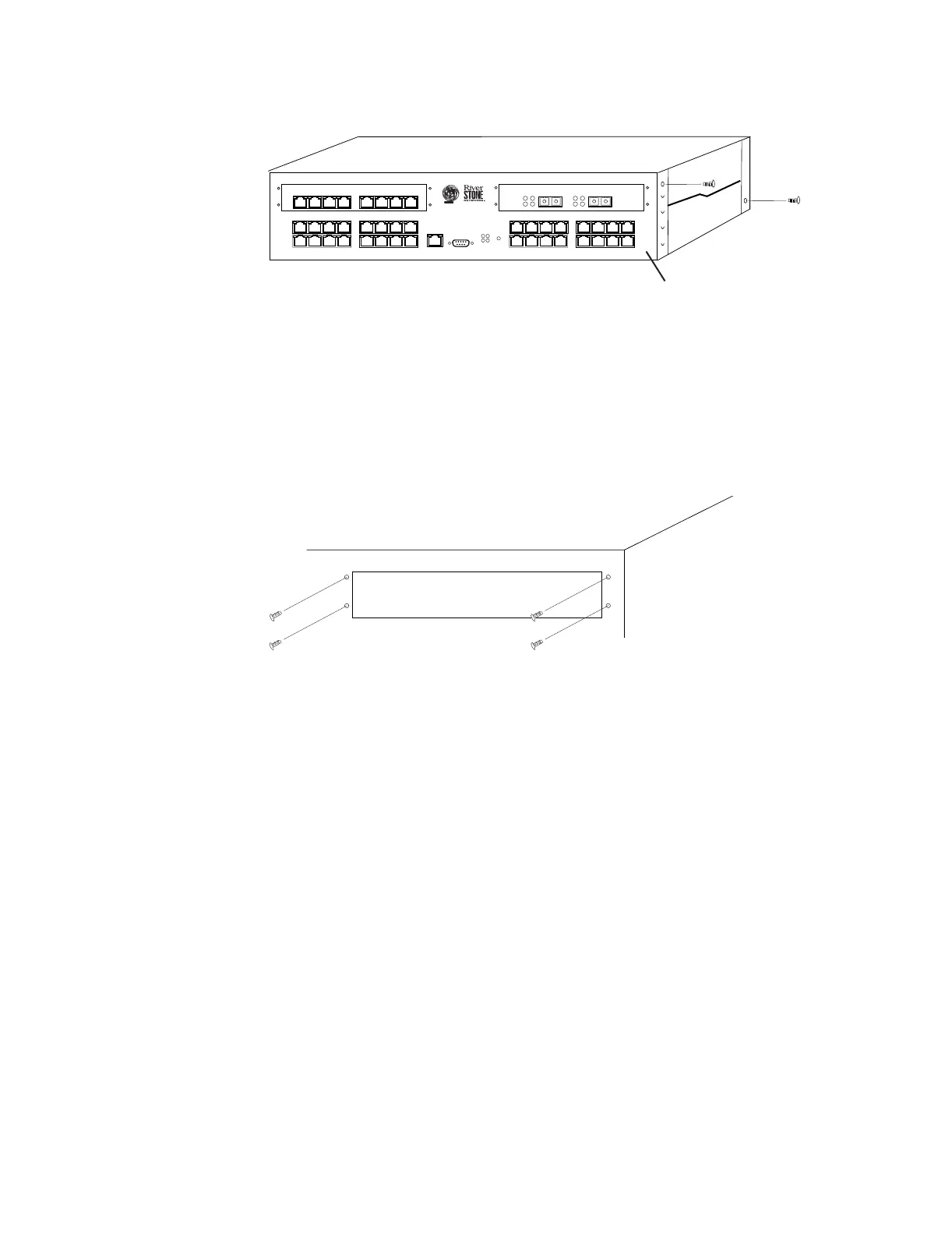
Figure 3-1 Removing the RS 3000, RS 3x00 or RS 3200’s cover
5. Slide the cover away from the front of the RS 3000, RS 3x00 or RS 3200 about one-half inch
(1/2”), then lift the cover away. Be careful not to damage or remove any EMI gaskets around the
edges of the cover.
6. Use the #2 Phillips-head screwdriver to remove the four mounting screws that secure the cover plate
to the expansion slot (see Figure 3-2). Be careful not to damage or remove any EMI gaskets around
the edges of the expansion slot opening.
Figure 3-2 Removing the cover plate (view from outside chassis)
7. Install the line card’s face plate:
Standard Face Plate – From the inside of the chassis, line up the four holes in the line card’s face plate with
the corresponding holes around the expansion slot. Use the screws provided and the #2 Phillips-head
screwdriver to affix the line card’s face plate to the chassis.
Extended Face Plate – From the inside of the chassis, place the face plate on top of the motherboard. Align
the extended face plate so that the four holes around the front of the face plate align with the four holes around
the expansion slot, and the four notches of the extended part are directly over the four stand-offs on the
motherboard (see Figure 3-5). You may need to gently push the extended face plate down while lining up the
first of the face plate screws. Use the screws provided and the #2 Phillips-head screwdriver to affix the line
card’s face plate to the chassis.
21
1000BASE-SX
87654321
10/100BASE-TX
3
4
CONSOLE
10/100 MGMT
OK
ERR
DIAG
HBT
G2M-HTXA2-08 G2M-GSXA1-02
Tx
Rx AN
LinkTx
Rx AN
Link
1
2
RST
RS 3000
Faceplate
 Loading...