26
NOTE-MH01-EN rev05
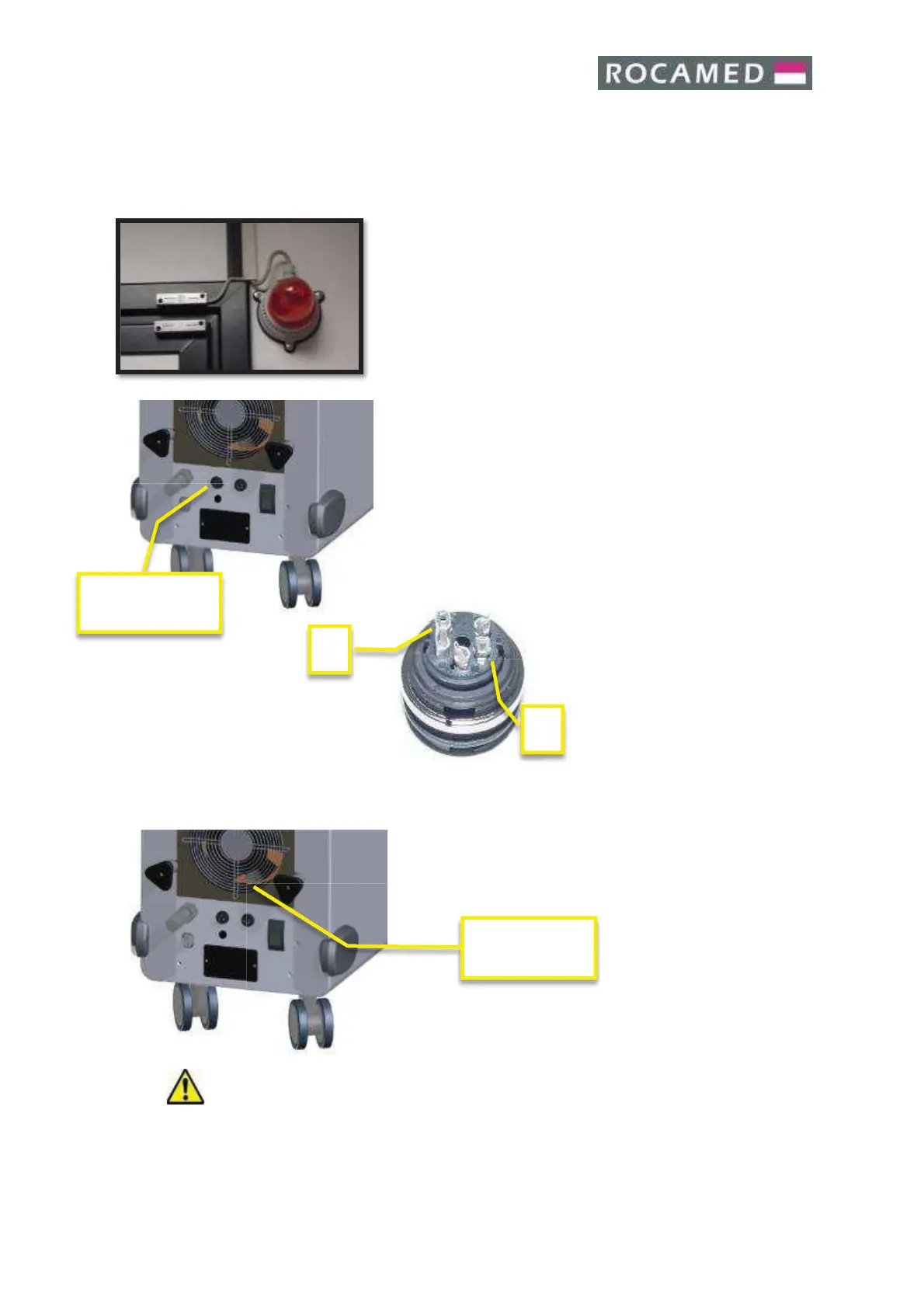
4.2.7 Remote interlock connection
According to IEC 60825-1 all laser devices must be equipped with a remote block
connector connected to the access door room to block the emission of the laser when it
is open.
A suitable switch shall be prepared by the client on the access
door room where the device will be installed: when the door
is closed the switch will give consent through a closed contact;
in the case of multiple access doors each have the its own
switch, whose contacts are connected in series.
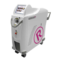
The remote interlock cable must be connected to a lamp
mounted near the door. The lamp should light when the laser
is activated and the door of the working area is closed. The
lamp connected to the remote interlock cable is shown in the
picture
The contact or the series of contacts will be led by a suitable
cable near the laser, where the specific connector will be
connected during installation. Internal pins (1 and 2) as shown
in the picture below:
4.2.8 Footswitch connections
The footswitch is used to start the laser emission.
Double (Options) or Single pedal
Warning: Do not wrap the footswitch with any plastic (or other material) film or cover
bag, unless authorized by the manufacturer. The unauthorized use of wrapping bags/films
may block the pedal in pressed position and cause unwanted laser emission.