Rockwell Automation Publication 520-UM001K-EN-E - August 2021 89
Chapter 3 Programming and Parameters
Options
24 “Logic In 1”
(1)(2)
Logic function input number 1. May be used to control the relay or opto outputs (t076, t081 [Relay Outx Sel] and
t069, t072 [Opto Outx Sel], options 11...14). May be used in conjunction with StepLogic parameters L180...L187 [Stp Logic
x].
25 “Logic In 2”
(1)(2)
Logic function input number 2. May be used to control the relay or opto outputs (t076, t081 [Relay Outx Sel] and
t069, t072 [Opto Outx Sel], options 11...14). May be used in conjunction with StepLogic parameters L180...L187 [Stp Logic
x].
26 “Current Lmt2”
(2)
When active, A485 [Current Limit 2] determines the drive current limit level.
27 “Anlg Invert” Inverts the scaling of the analog input levels set in
t091
[Anlg In 0-10V Lo] and t092 [Anlg In 0-10V Hi] or
t095 [Anlg In4-20mA Lo] and t096 [Anlg In4-20mA Hi].
28 “EM Brk Rlse” If EM brake function is enabled, this input releases the brake. See t086 [EM Brk Off Delay] for more information.
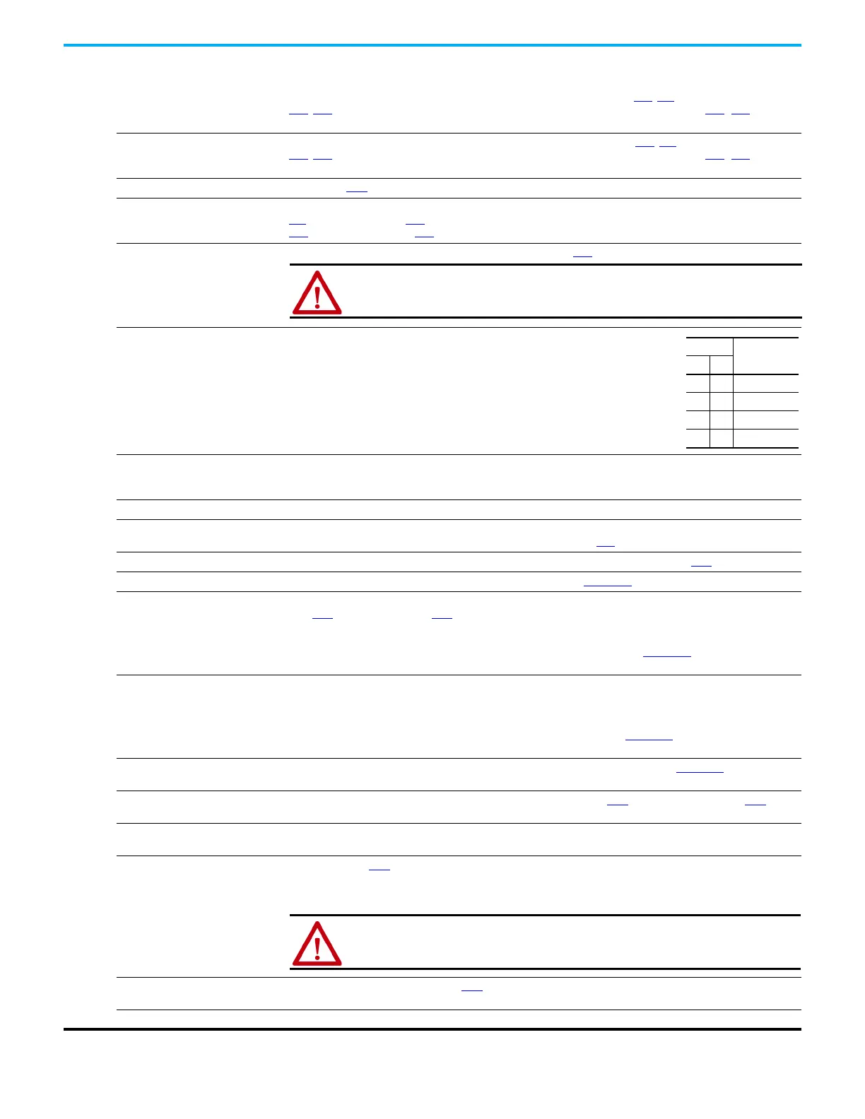
29 “Acc/Dec Sel3”
(1)
If active, determines which Accel/Decel time is used for all ramp rates except jog.
Used with option 11 “Acc/Dec Sel2” for the Accel/Decel times listed in this table.
30 “Precharge En” Forces drive into precharge state. Typically controlled by auxiliary contact on the disconnect at the DC input to the
drive. If this input is assigned, it must be energized for the pre-charge relay to close and for the drive to run. If it is de-
energized, the pre-charge relay opens and the drive coasts to a stop.
31 “Inertia Dcel” Forces drive into Inertia Ride-Through state. The drive attempts to regulate the DC bus at the current level.
32 “Sync Enable” Must be used in order to hold the existing frequency when Sync Time is set to enable speed synchronization. When this
input is released the drive accelerates to the commanded frequency in A571
[Sync Time].
33 “Traverse Dis” When an input is programmed the traverse function is disabled while this input is active. See A567 [Max Traverse].
34 “Home Limit”
(2)
In Positioning mode, indicates the drive is at the home position. See Appendix E for more information on Positioning.
35 “Find Home”
(2)
In Positioning mode, causes the drive to return to the Home position when a Start command is issued.
Uses A562 [Find Home Freq] and A563 [Find Home Dir] until the “Home Limit” input is activated. If it passes this point,
it then runs in the reverse direction at 1/10th the frequency of [Find Home Freq] until the “Home Limit” is activated
again. As long as this input is active, any start command causes the drive to enter the homing routine. Only functions if
in Positioning mode. Once the Find Home routine has finished, the drive stops. See Appendix E for more information on
Positioning.
36 “Hold Step”
(2)
In Positioning mode, overrides other inputs and causes the drive to remain at its current step (running at zero speed
once it reaches its position) until released.
While in “Hold”, the drive ignores any input command which would normally result in a move to a new step. Timers
continue to run. Therefore, when the Hold is removed, the drive must see any required digital inputs transition (even if
they already transitioned during the hold), but it does not reset any timer. See Appendix E
for more information on
Positioning.
37 “Pos Redefine”
(2)
In Positioning mode, resets the home position to the current position of the machine. See Appendix E for more
information on Positioning.
38 “Force DC” If the drive is not running, causes the drive to apply a DC Holding current (A435
[DC Brake Level], ignoring A434 [DC
Brake Time]) while the input is applied.
39 “Damper Input” When active, drive is allowed to run normally.
When inactive, drive is forced into sleep mode and is prevented from accelerating to command speed.
40 “Purge”
(1)
Starts the drive at A433 [Purge Frequency] regardless of the selected control source. Supersedes the keypad Control
function as well as any other control command to take control of the drive. Purge can occur, and is operational, at any
time whether the drive is running or stopped regardless of the selected logic source selection. If a valid stop (other
than from comms or SW enable) is present, the drive will not start on the purge input transition.
41 “Freeze-Fire” When inactive, will cause an immediate F094
“Function Loss” fault. Use to safely bypass the drive with an external
switching device.
42 “SW Enable” Works like an interlock that has to be active for the drive to run.
Programmable Digital Inputs (Continued)
ATTENTION: If a hazard of injury due to movement of equipment or material
exists, an auxiliary mechanical braking device must be used.
Option
Description
29 11
00Acc/Dec 1
0 1 Acc/Dec 2
1 0 Acc/Dec 3
11Acc/Dec 4
ATTENTION: If a hazard of injury due to movement of equipment or material
exists, an auxiliary mechanical braking device must be used.

 Loading...


