1.2 Assembly of the MCP-Detector
The assembly should take place under clean and dry conditions.
List of Detector Assembly Parts
• ceramic rings, partially metal coated (for DLD40, DLD80 and HEX80/HEX75) or metal rings/plates
• two multi-channel plates, selected for chevron configuration, matched in resistance
• metal spring clamps (for DLD40, DLD80 and HEX80/HEX75)
• plastic M3 screws with nuts (for DLD40, DLD80 and HEX80/HEX75 only during assembly of the MCP holder)
*
• 1 delay-line anode
• Assorted small parts for cable connections (optional)
If you have purchased the detector with the “readily mounted” option (only available with FT12(16)TP/xxx flange mounting) you need to remove
the detector case (and ma return it to
RoentDek for receiving a refund). All connections to the anode should already be in place but the MCP
must be mounted according to the directions below. You will also have to verify all anode connections and check for absence of shorts which may have
occurred during transports. Therefore, please review the following instructions even if you have received a “readily mounted” anode.
For DLD40, DLD80 and HEX80 the MCP holder with rear ceramic ring may already be placed on the delay-line anode, it is
fixed by the retractable “shields” in a position that should be resumed after assembly of the MCP stack. If the rear ceramic ring
is not pre-mounted (i.e. for transport safety reasons) please test-mount it now and observe the relative angle of the metallization
structure. You will in any case have to remove it for assembling the MCP stack (see below). After this assembly, the rear ceramic
ring has to be in about the same orientation as shown in Figure 1.3.
All parts, especially the MCP and the wire anode structure should be handled with great care. The wire array is very delicate.
The ceramic rings should not be exposed to exceeding mechanical or thermal stresses. The MCP surfaces are very sensitive and
should never be touched or scratched. Some “optical defects” may be seen on the MCP surfaces after removing them from the
transport packing. Unless the MCP are broken (transport damage) this will not affect performance within specifications. Please
read the whole assembly section before starting the mounting, see also Appendix for MCP handling.
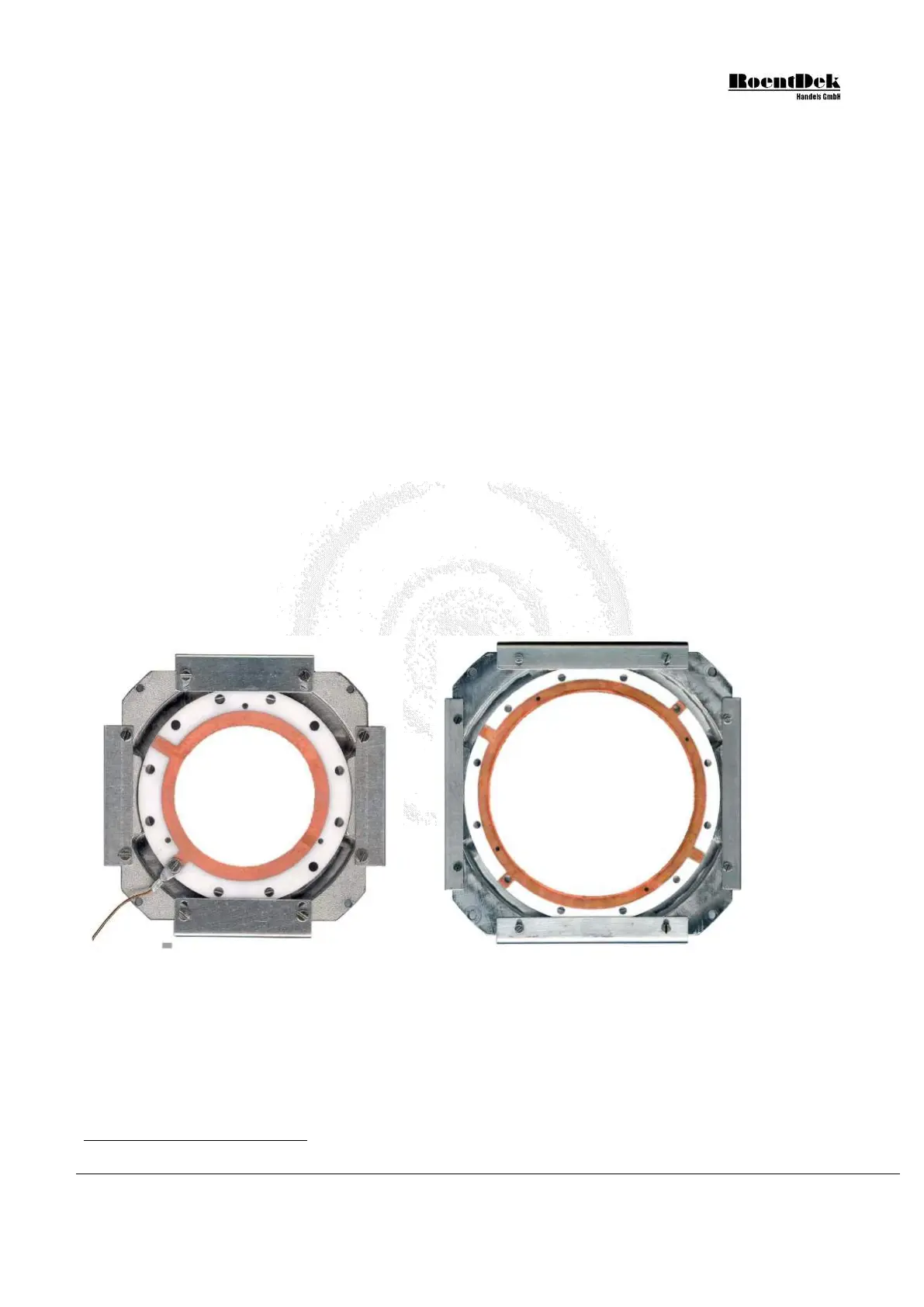
Figure 1.3: Orientation of the rear ceramic ring on the Delay-line assembly (DLD40, DLD80). For HEX80/HEX75
the orientation is similar, but there is only one pair of flat “shields”.
1. Verify with an Ohm meter that no dust particles have electrically shortened the anode wires. The anode contains one
pair of wires for each special direction. Neither the two wires of one pair nor the wires of the different layers should
be in contact (>10MΩ). Also verify that there is no electrical connection between the wires and the holder plate. Dust
particles can be removed by gentle blow with dry air or a soft brush. Check the resistance of each of the 4 wires. From
one end to the other it should be around 5Ω for the DLD40, 12Ω for the DLD80, 17Ω for the HEX80/HEX75,
*
For DLD120 and HEX120: 6 PEEK M3 screws and 3 plastic M3 rods (the latter only during assembly of the MCP holder)
MCP Delay Line Detector Manual (11.0.1304.1) Page 11 of 83