a) no jumpers: inputs + and – are active (differential) with 100Ω impedance. Please observe the polarity
b) jumper on JP6/JP9: input – (inverting 50Ω impedance to ground); can be used for positive input signals
c) jumper on JP5/JP8: input + (non-inverting 50Ω impedance to ground); can be used for negative input signals
Default settings are: ch1 and ch2 as (b) and ch3 to ch8 as (c), for ATR19-2: ch1 as (b) and ch2 as (c) when used with a
DET40/75 or both channels as (c) for read-out of a delay-line anode.
If you want to change these settings please refer to chapter 3.5 and/or 3.6.
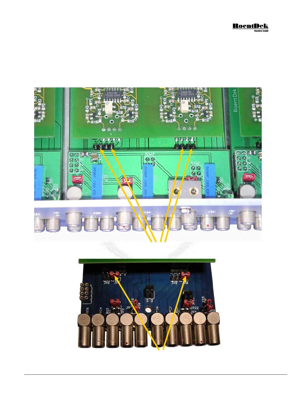
Figure 3.3: ATR19 with input settings for differential input (no input jumpers set)
Figure 3.4: ATR19 base board with input jumper settings for signal input through
the “+” LEMO input (
50
impedance to ground, non-inverting, for negative
signal input). The level control board was removed here for better view.
MCP Delay Line Detector Manual (11.0.1304.1) Page 37 of 83