Details of the HM1(-B) operation is given in a separate manual. HM1 modules cannot be operated with x64 OS.
(This product line is discontinued!)
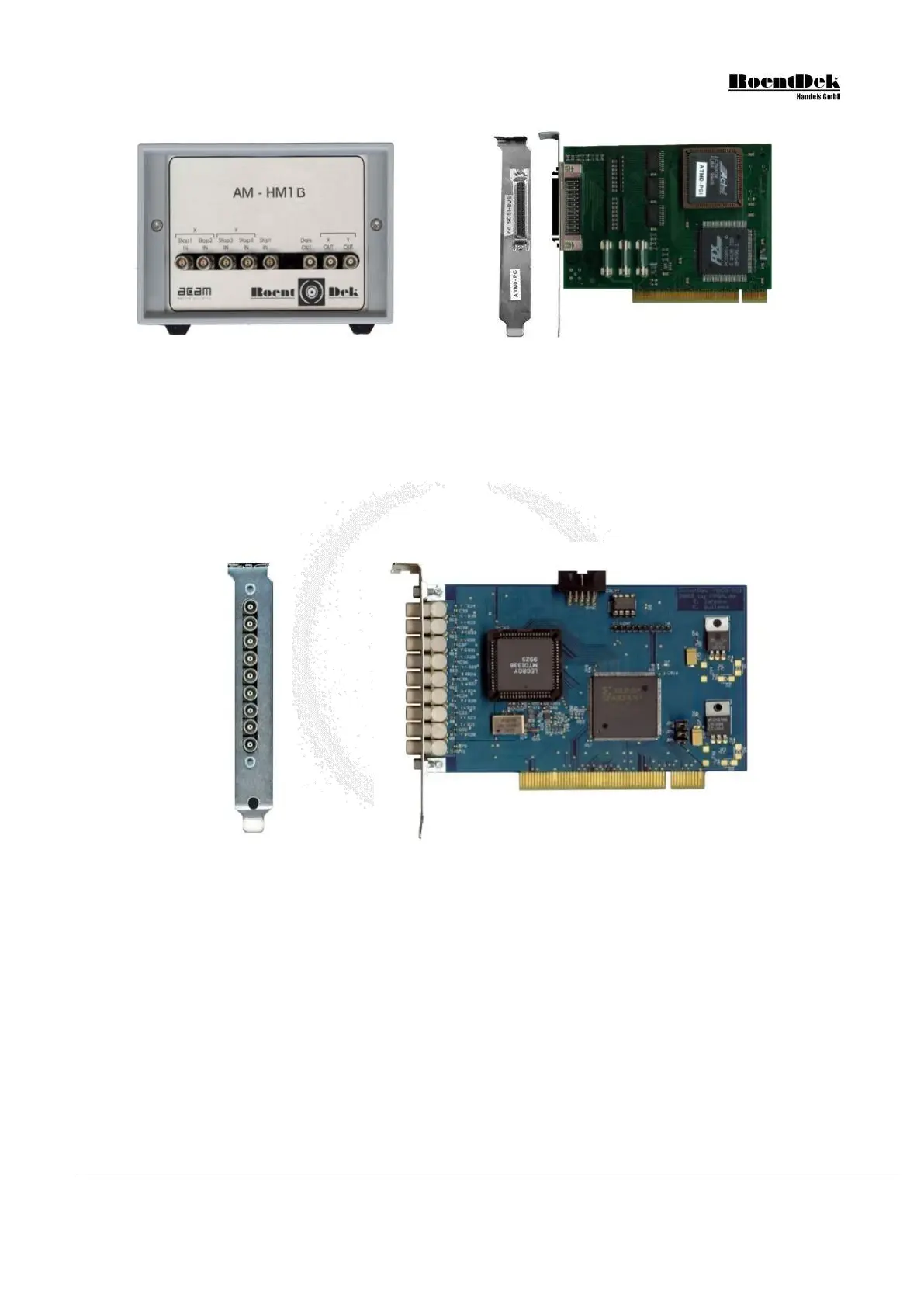
The TDC8 is based on the LeCroy MTD133B-chip (production discontinued). It has an input for common start or common
stop operation and 8 channels. It operates only in “transparent mode” (list mode) and can collect up to 16 hits per channel.
The resolution is 500ps and the range is 16 bit. The input level is NIM. Up to three TDC8 can be combined. Especially, two
of the TDC8 can be coupled to an effective 15 (ISA) or 16 (PCI) channel single start/stop TDC.
Figure 4.5: TDC8PCI2 board
For details of the TDC8 module versions please refer to the separate manual.
4.2 Hard- and Software Installation
• Shut down your computer
• For your devices safety, turn off the power to your computer and all peripheral devices.
• Drain static electricity from your body by touching the metal chassis (the unpainted metal at the back of your
computer)
• For your personal safety, remove the power cord from your computer
• Remove the cover of the computer as described in your computer’s manual.
Figure 4.3: HM1-B/T and HM1-B front panel
Figure 4.4: PCI interface card
MCP Delay Line Detector Manual (11.0.1304.1) Page 55 of 83