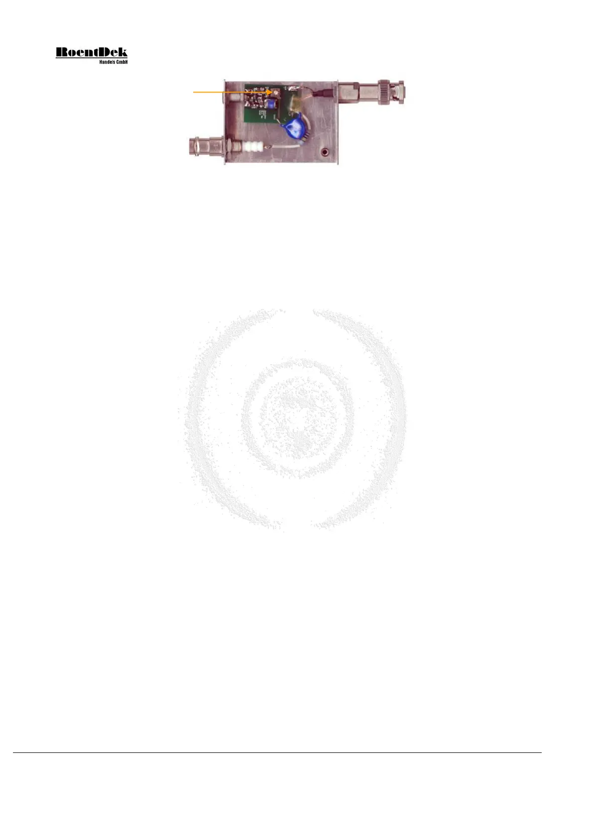
Figure 2.7: Single HF-signal-de-coupler plug (HFSD) with LEMO output and in-line poti
The
HF-signal-de-coupler plugs
can also contain an additional resistor to ground which provides the HVT function (see
RoentDek power supply manual which may be appended to this document).
2.5 Operation of the MCP detector with delay-line (or timing) anode
This introduction to the MCP detector operation shall only give general info on the detector startup and basic function
verification. For fine-tuning please refer to the specific sections describing the front end electronics (amplifier and timing
circuits), digital read-out and high voltage supply, e.g. as optionally available from
RoentDek.
If you have purchased a detector for operation at higher voltages than 4kV please refer to the separate manual.
Initial Startup Procedure
After installation of the detector and verification of all connections it is advisable to verify the absence of electronic noise on
the detector parts, i.e. on the MCP front/back and anode contacts. Continuous noise should be <1mV peak-to-peak. Noise
should be checked by connecting an amplifier (band width about 100MHz or higher) to the outputs of the signal decouplers
(high voltage supplies turned off) and verifying the amplified output on an oscilloscope (taking into account the amplification
factor to judge the noise amplitude). If you should find a too-high noise level (or no noise at all) this may indicate erroneous
cable connections. External sources for noise may be found in the lab equipment and can be traced by turning off lab equipment
sequentially, or outside the lab/building (power stations, heavy machinery operating, radio stations …).
This test can already be done before starting the vacuum pumps which may also contribute to the noise level.
For supplying the MCP operation voltages it is strongly recommended to use low-ripple power supplies with current limitation
and fast shutdown for protection (as available from
RoentDek).
Always evacuate the vacuum chamber slowly (50mbar/sec) in the presence of an MCP detector. The maximum recommended
operating pressure for the detector is 2x10
-6
mbar).
Before applying any voltage to the detector for the first time it should be verified that:
- the detector is in appropriate vacuum conditions (< 10
-6
Torr) for at least 24h, see also Appendix
- all connections inside the vacuum are complete and have been carefully verified, also for absence of shorts
- safe distances are kept or sound insulation is installed between all biased parts of the detector (including attached
cables) and the chamber wall and or other metal parts on ground or other potentials (i.e. mounting gear)
- safe distances are kept between the MCP front (and optional mesh) contacts and exposed cable parts to any other part
of the detector (double-check also exposed cable/connector parts on the vacuum feedthrough)
- all feedthroughs, decoupling circuits and high voltage cables are rated for the targeted maximum detector voltage,
- potential EM noise sources are turned off
- UV sources, high power laser sources, charged particle sources (also ion gauges or ion pumps, discharge gaps) in the
detector’s vacuum recipient are turned off
New MCP or MCP that have been exposed to atmospheric pressure for a long time must be biased very slowly in steps of
100V every few minutes. During this, the current should be monitored for possible deviations from linear current-to-voltage
characteristics (indicating a problem). As the operation voltage is approached, the amount of “dark counts” (MCP signals in
absence of any particle/photon source) should be monitored. This requires a low noise level (see above). To monitor the noise
and the presence of signals, an amplifier should be used for verifying signals from the MCP front or MCP back contact with
an oscilloscope. A low dark count rate (typically <100counts/sec, randomly distributed) will at some point already indicate that
the MCP is operating normally, especially when the mean pulse height increases/decreases according to the MCP bias setting.
Page 30 of 83 MCP Delay Line Detector Manual (11.0.1304.1)