set (with DLATR2.0). Double-hit dead-time of the CFD-outputs is about 20ns, depending on the input signal width. Since the
amplifier inputs are internally not tolerant to both signal polarities (no bipolar amplification), it is required to feed signals into
the inputs of corresponding polarity. Therefore positive input signals (e.g. the signal from the MCP) must be connected via the
inverting (-) input and negative signals must be connected via the non-inverting (+) input. To ensure proper input impedance
of single polarity signals the other input of the internal amplifier should be terminated to ground (see Chapter 3.1).
The recommended readout version of the
RoentDek delay-line detectors involves the FT12(16)-TP plug with internal signal
transformers for the delay-line signals. For applications where only the single particle timing is of importance (e.g. with
DET40/75) a FT4TP-type read-out in combination with the ATR19-2 is recommended. The physical characteristics of the
ATR19-2 are described in Chapter 3.6.
When the ATR19 is delivered, channel 1 and 2 are by default prepared for positive input polarity (inverting) and the other
channels (used for the delay-line signals) for negative (non-inverting) signal polarity. (ATR19-2 default: ch1 for positive input
polarity (inverting) and ch2 for negative (non-inverting) signal polarity). If the voltages to the detector are supplied in the
recommended way the signal from the MCP front or back contact (positive) has to be connected to ch1- or ch2- and the delay-
line signals to ch3+ to ch6+ (or ch8+). In case of DET40 and ATR19-2: the signal from the MCP front or back contact
(positive) has to be connected to ch1- and/or the signal from the timing anode (negative) has to be connected to ch2. Changing
these settings requires to open the ATR19 module (see Chapter 3.5 and for ATR19-2 also Chapter 3.6).
3.1 Signal inputs and amplification
The ATR19 hosts three or four DLATR boards (one in case of ATR19-2). Each board has two independent channels for
amplification and timing discrimination. Each differential amplifying stage has 100Ω impedance (2x50Ω to ground) and a
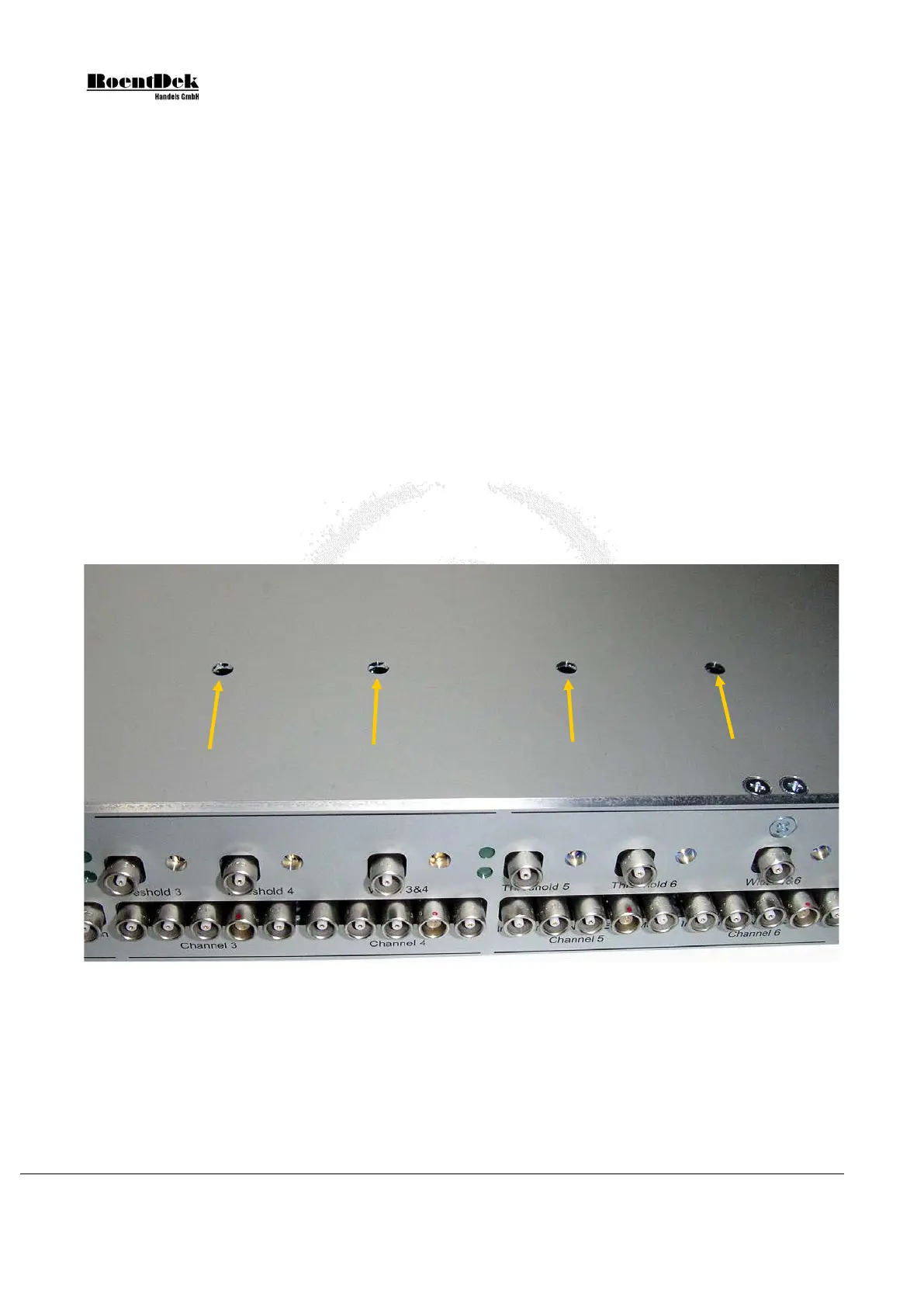
selectable differential amplification gain between 20 and 100. The gain can be adjusted by a potentiometer (“poti”) on each
board and channel independently through holes in the top lid of the ATR19 module.
Figure 3.2: Top lid of ATR19 with holes to reach the gain potentiometers.
Turning clockwise: amplifier gain is increased, turning counter clockwise: gain is decreased
(for ATR19-2 refer to Chapter 3.6)
The input to each amplifier is provided AC-coupled via coaxial LEMO connectors with 50Ω impedance. It is important to note
the actual input settings for each individual channel inside the ATR19, i.e. the position of the termination jumpers JP5, JP6
(odd channel numbers of the ATR front panel) JP8 and JP9 (even channel numbers):
Page 36 of 83 MCP Delay Line Detector Manual (11.0.1304.1)