Once you have reached about 70% - 80% of the default MCP stack bias you can start observing dark counts (and potentially
counts from particles) with low pulse height (10mV, positive polarity, few ns width). From now on the signal from MCP back
should be verified on an oscilloscope. Unless your decoupling circuit’s signal output is internally DC-terminated (the
RoentDek decouplers are) you must turn down the voltage before connecting a cable for signal verification. Otherwise a
discharge may occur and potentially damage the detector and/or the follow-up electronics.
(If you had to turn down the voltage you can steadily increase the voltage again with a ramp speed of up to 1000V per second
to the value which was reached before).
One should never connect an oscilloscope directly to the signal output of a decoupler because a discharge may
damage it. Instead one should route the signal through an amplifier. The amplifier input may also be destroyed by a discharge
but it is usually easier to repair.
RoentDek decoupling circuits and amplifier inputs contain several safety circuits (and are
more robust than most other circuits), especially when used in combination. However, they may be damaged in some cases,
too. A repair procedure and costs are well defined, please contact
RoentDek in such an event.
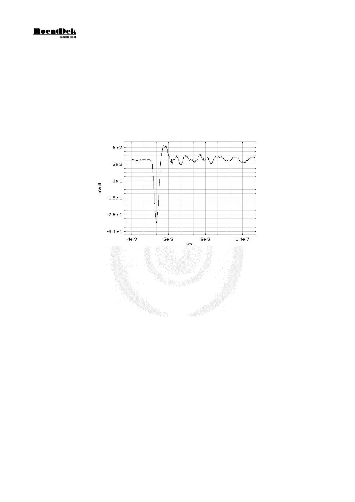
Figure 2.8: Typical amplified pulse shape from the MCP after processing with an inverting amplifier
(here: analog monitor output from a
RoentDek ATR19 module).
If you will observe dark counts at a decent rate you may further increase the voltage in steps and watch their growing pulse
height with each step until you reach the default voltage. Generally, MCP stacks can be operated with a relative bias voltage up
to about 1300V for each MCP in the stack for MCP with L/D 60:1 or 80:1 (only 1000V per MCP with L/D of 40:1, for 80:1
even higher bias up to 1500V per MCP may be required). Applying lower bias on the MCP often yields sufficient performance
and can increase the lifetime of the MCP stack. Higher voltages are not recommended and will only improve the performance
if the amplifiers still have sufficient dynamics.
At this point one should also connect the delay-line anode (or timing anode) signal output(s) to amplifiers (see safety
consideration above before that) and verify all signals on the oscilloscope. Signals from the delay-line or timing anode look
similar like MCP signals but have negative polarity. If anode signals should be “missing” or noisy please verify their connections.
You may be required to vent the vacuum chamber and open it for that. However, most wiring errors can be found by verifying
connections with an Ohm meter or passing a test pulse from an external source (e.g. the
RoentDek APG1) through the
delay-line layers.
Always make sure to turn high voltage off before venting the chamber.
Even if you have vented the chamber only for a short time you should allow at least 8 hours of pumping at sufficient pressure
level. You may raise the voltage on the MCP up to the level that was reached once before in much shorter time (100V/sec),
however, be aware of the risk for discharge events after the detector or the cables have been touched or moved. Verify all
signals until the detector operates normally.
Depending on the particle species to be detected you will have to shift all detector voltages with respect to ground, maintaining
the relative detector potentials at about the same levels.
Page 32 of 83 MCP Delay Line Detector Manual (11.0.1304.1)