• Locate a free PCI slot in your computer, and firmly insert the card into the selected slot. To avoid damaging your
hardware, insert the card only into a slot with the same bus type as the card. Inserting the card into any other type of
slot can damage your card, your computer, or both.
• Firmly secure the adapter with a screw (or clip), to ensure that the adapter is properly grounded to the computer’s
chassis.
• Replace the cover of the computer as described in your computer’s manual.
For a detailed description and how to install TDC8HP drivers please refer to the TDC8HP manual
• Shut down your computer.
• For your devices safety, turn off the power to your computer and all peripheral devices.
• Drain static electricity from your body by touching the metal chassis (the unpainted metal at the back of your
computer).
• For your personal safety, remove the power cord from your computer.
• Remove the cover of the computer as described in your computer’s manual.
• If necessary adjust the I/O address setting on the I/O card to a free I/O address (ISA-I/O card version only). Do
not forget to adjust parameter 1 in your .ccf file to this I/O address or set the value of this parameter to 0 to
automatically determine the I/O address.
• Locate a free ISA/PCI slot in your computer, and firmly insert the card into the selected slot. To avoid damaging our
hardware, insert the card only into a slot with the same bus type as the card. Inserting the card into any other type of
slot can damage your card, your computer, or both.
• Firmly secure the adapter with a screw (or clip), to ensure that the adapter is properly grounded to the computer’s
chassis.
• Replace the cover of the computer as described in your computer’s manual.
• Connect the HM1 module with the I/O card using the connection cable. The three green LED on the HM1 module
should be on now.
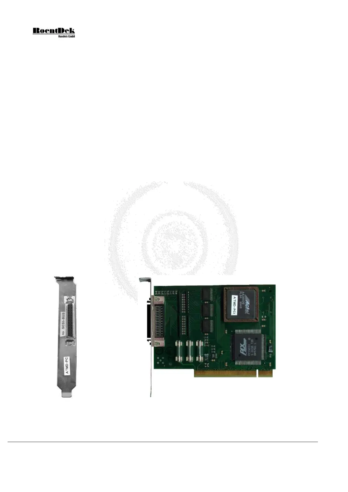
Note that the I/O card is not using SCSI signaling standard, although it has a SCSI socket and cable.
Major damage to your hardware will occur if you connect a SCSI device to the HM1 interface card or the HM1 to an
SCSI controller.
Figure 4.6: Side and input panel view of the HM1 - I/O-board (PCI)
Page 56 of 83 MCP Delay Line Detector Manual (11.0.1304.1)