3.2 The DLATR board
The ATR19 module contains boards of type DLATR, which are occasionally updated in the circuit design without altering
their function. Currently DLATR+ and DLATR2.0 boards are supplied. The board can easily be exchanged. To modify
settings on the boards or exchange the boards please refer to Chapter 3.5. The amplification gain can be changed without
opening the ATR19 unit.
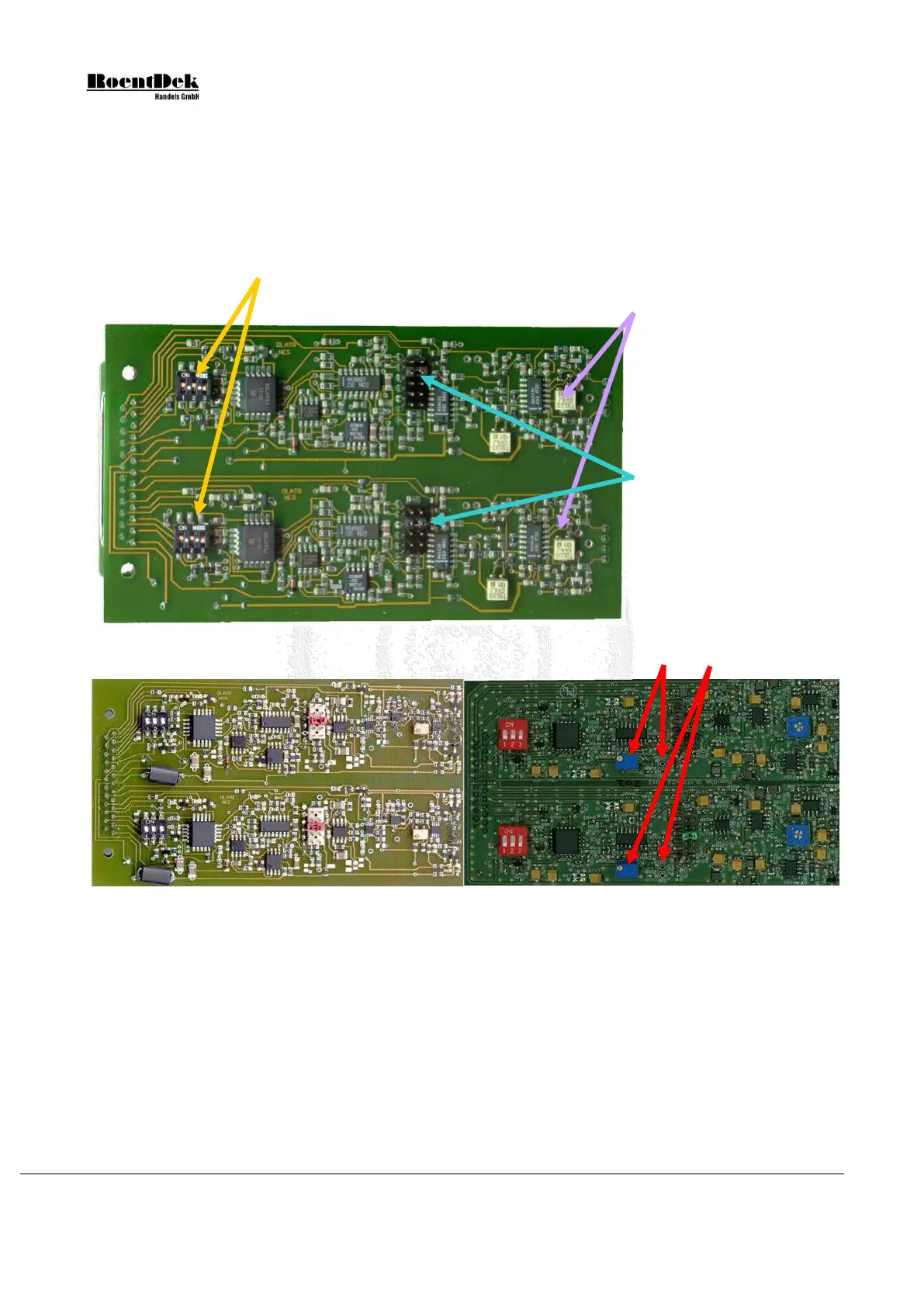
These 3 switches for each channel define the output level NIM or ECL (number 3 must
always be „off“) 1: „on“ ECL, „off“ NIM
2: „on“ ECL, „off“ NIM
Figure 3.5: DLATR amplifier and constant fraction discriminator boards.
The marked potis
arrows (2kΩ for the DLATR+)
adjust the amplification.
Higher resistance corresponds
to lower amplification (not
linear).
The marked jumpers, see blue
arrows, define the internal
CFD-delay. The figure shows
the default position (8ns for
DLATR
DLATR+). From bottom to
top: 2,4,6,8,10ns
For DLATR2.0: the red arrows
mark the walk potis and the test
points (factory set to 12-14mV)
Figure 3.6: DLATR+ version (left) and DLATR2.0 (right)
If you insert a board make sure that the settings on the board are according to the requirements (e.g. signal level NIM or ECL).
The switches have to be set according to the desired timing signals levels from the ATR19 module.
Always switch off the power when inserting or retracting a DLATR board or changing settings on a board.
3.3 CFD controls and outputs
The ATR19 has the following inputs, outputs and controls for each channel:
2 LEMO connectors In+ and In- for signal input (see Chapter 3.1)
3 LEMO connectors for signal outputs:
Mon analog output signal, i.e. the amplified signal before the CFD-stage.
Page 38 of 83 MCP Delay Line Detector Manual (11.0.1304.1)