It is also possible changing the internal resistor to a value so that the desired voltage on MCP front (or back) is generated only
by applying the bias on the other MCP side (passive HVT use). The corresponding value of R
HVT
can be derived from Equation
5.1.
Important: only use resistors with sufficient voltage and power rating.
If you need help in determining R
HVT
for passive HVT use or finding adequate resistors please contact RoentDek.
For applications with demands for slow heavy ion or negative ion detection please contact
RoentDek for special detector
mounting, signal decoupling and high voltage supply rated up to 10kV.
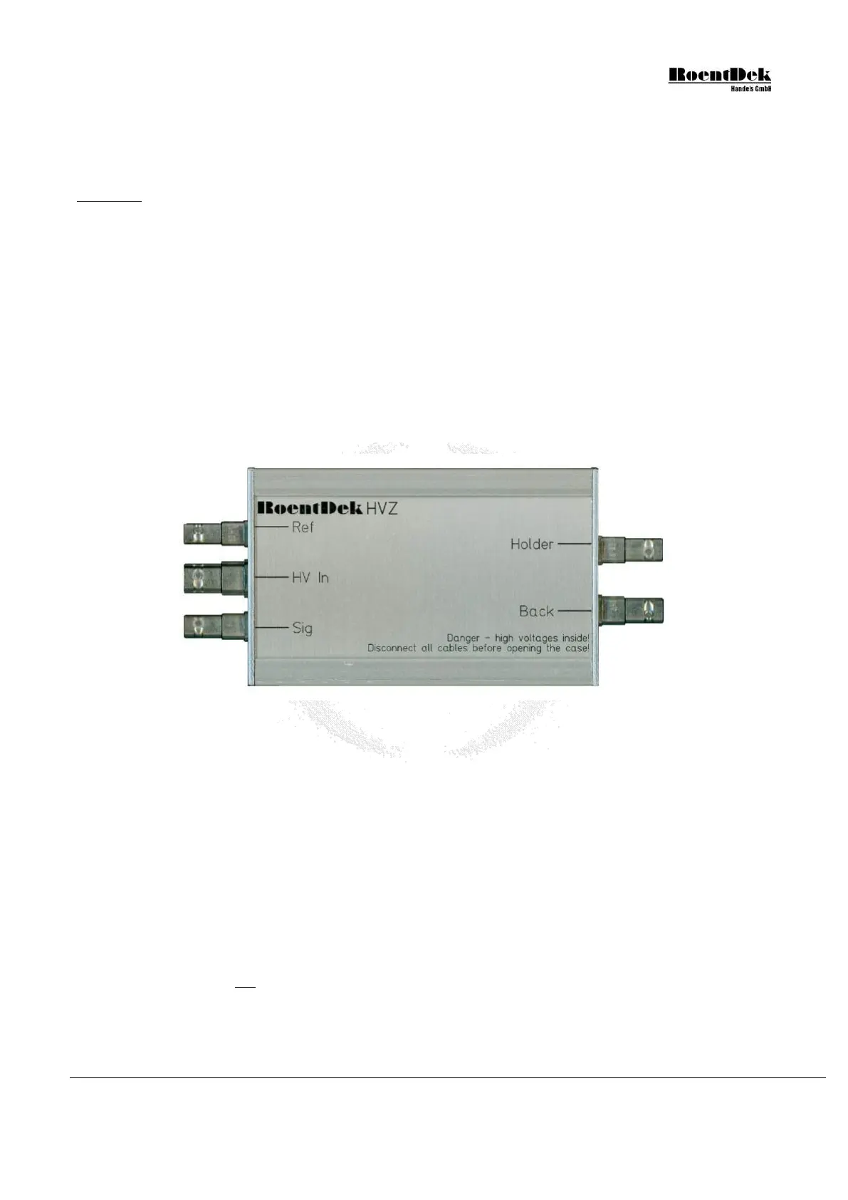
5.5 HVZ voltage divider unit
The RoentDek HVZ is a passive voltage divider box generating intermediate potentials in steps of 56V (+/-10%) for all
delay-line anode contacts and MCP back side of
RoentDek delay-line detector (and 39V nominally between the reference
and signal wire). It has one high voltage input socket (SHV) labeled “HV In” and four SHV output sockets for providing bias
to the MCP back side (U
MCP back
), “Holder” (U
H
) and the delay-line anode wires (U
ref
/U
sig
). Thus, only two potentials are to be
provided from high voltage supplies for biasing all detector contacts: U
sig
(via the “HV In” socket) and U
MCP front
, i.e. the MCP
front potential. The latter may also be produced by “terminating” MCP front via a
RoentDek HVT (see Chapter 5.4). Other
detectors like the
RoentDek DET40/75 can also be biased in this way using the HVZ.
Figure 5.9: HVZ with the SHV connector sockets.
Using the HVZ for detector bias is equivalent to applying a resistor divider chain for this purpose. The HVZ has the advantage
that the relative voltages set between MCP back, Holder and delay-line wires do not dependent on the absolute detector bias
with respect to ground (i.e. are independent from the choice of MCP front potential). This insures the proper voltage difference
between the MCP back side and the anode (wires) and at least near-optimal voltage setting for the DLD’s or Hex’ “Holder”
bias: its intermediate potential can be selected in steps of 56V (nominally) by jumper settings. A battery box is not needed when
using the HVZ, however, optional jumper positions also allow bias settings for the wires through a BA3 or other floating
battery units. The BA3 may also be used in combination with the HVZ for increasing the voltage difference between anode
wires and MCP back (see below).
Inside the HVZ a total voltage drop of up to a maximum set value (i.e. 260V) is generated as soon as appropriate electrical
current flows through the unit from the input SHV socket labeled “HV In” to the “Back” socket. This current can only flow if
there is an according potential difference maintained between the sockets and the current is drained by a resistor load connected
to the “Back” socket. This resistor may be a microchannel plate stack: The HVZ’ “Back” socket is physically connected to the
MCP stack’s back side input and the MCP stack’s front side must be kept at a less positive potential than the bias on “HV In”.
It is important to note that the relation between the current through the MCP stack and the voltage between “HV In” and
MCP front potentials is not linear, as long as it is lower than the HVZ’ set value. For calculating the nominal MCP back
potential (i.e. on the voltage input of a signal decoupler on MCP back contact) the set voltage needs to be subtracted from the
MCP Delay Line Detector Manual (11.0.1304.1) Page 75 of 83