Figure 3.17: How to remove the input fuse
Figure 3.18: Fuse holder
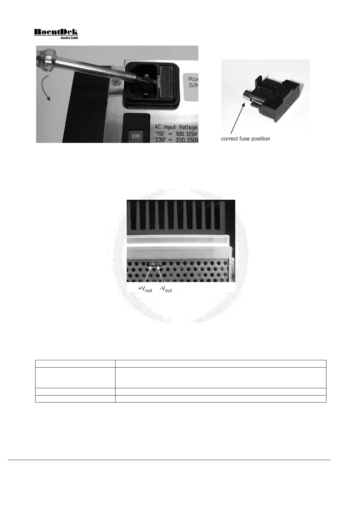
Output voltage adjustment
Both output voltages may be adjusted if necessary. The two potentiometers are accessible from the bottom side of the SPS1’s
casing (see Figure 3.19). For safety reasons use a fully insulated screwdriver to adjust the potentiometers.
Figure 3.19: Adjusting the output voltages (SPS1 seen from bottom side)
Maintenance and Troubleshooting
For cleaning, please use a clean, dry or slightly moist cloth only. Remove the power connection first. Do not use any chemicals
for cleaning. Always make sure that no liquids enter the case.
If any problems occur, disconnect any devices from the SPS1 power supply and directly measure the output voltages. You may
try to solve the problem using the following overview:
all output voltages missing
- input fuse broken (see Chapter 3.8.2)
- both internal output fuses broken (overload or short-circuit has occurred)
one output voltage missing
- internal output fuse broken (overload or short-circuit has occurred)
- re-adjustment of the output voltage needed (see Chapter 3.8.2).
Table 3.3: Troubleshooting
Please note that the green power switch may light only very dim when the SPS1 is operated at 100-125V.
Page 48 of 83 MCP Delay Line Detector Manual (11.0.1304.1)