2.2 Connecting the Signal Cables to a Feedtrough Flange
In the following the connection scheme to the FT12 feedthrough flange is described. This flange is used for airside coupling
to the FT12TP(hex) signal decoupling plugs. The following connection schemes are also compatible with earlier read-out
concepts (FT12/16 with DLATR6/8). For the DLD detectors the FT12 offers also feedthrough leads for the remaining
detector contacts (i.e. for the MCP and Holder), with HEX detectors require additional feedthroughs like in the FT16 product
assembly.
Unless you have purchased the flange mounted option you will usually receive a spool of Kapton isolated cables (for DLD)
which can be used in UHV. You need to produce single and twisted-pair cables of sufficient lengths as described before in this
section. The cables should only be as long as necessary. Especially the quality (amount of “ringing”) of the MCP signal is usually
better if the connection cable is very short. If you have purchased a Hexanode without flange mounting option you have receive
a set of cables with two parallel wires (about 0.5m long) for connecting the Hexanode delay-line.
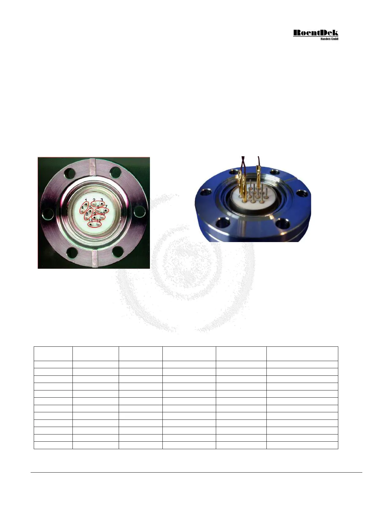
For the DLD connect all 8 cables from the delay-line and the other 3 (or 4) high voltage cables (MCP front, MCP back, anode
holder plate and optional mesh) from the vacuum side of the feedthrough flange. Figure 2.3 shows the FT12 flange from the
vacuum side.
Figure 2.3: Pin numbers at the FT12 flange (the air-
side guiding groove points upwards) and cable
connections.
Unless you have purchased the flange mounted option you will usually receive a spool of kapton-shielded cables which can be
used in UHV. You may need to produce single and twisted-pair cables of sufficient lengths as described before. The cables
should only be as long as necessary. Especially the MCP signal quality (amount of “ringing”) is usually improved if the
connection cables are kept as short as possible.
For the DLD connect all 8 cables from the delay-line and the other 3 (or 4) in vacuum cables for MCP front, MCP back, anode
holder plate and optional mesh from the vacuum side of the 12-pin feedthrough flange according to Table 2.1. In case of a
Hexanode detector, the 12-pin feedthrough is only used for the anode terminals (according to Table 2.2 while the other detector
contacts are connected via separate feedthroughs, e.g. the FT4 which is part of the FT16(TP) or via individual coaxial SHV or
MHV feedthroughs.
Table 2.1: FT12TP pin description for DLD detectors
MCP Delay Line Detector Manual (11.0.1304.1) Page 25 of 83