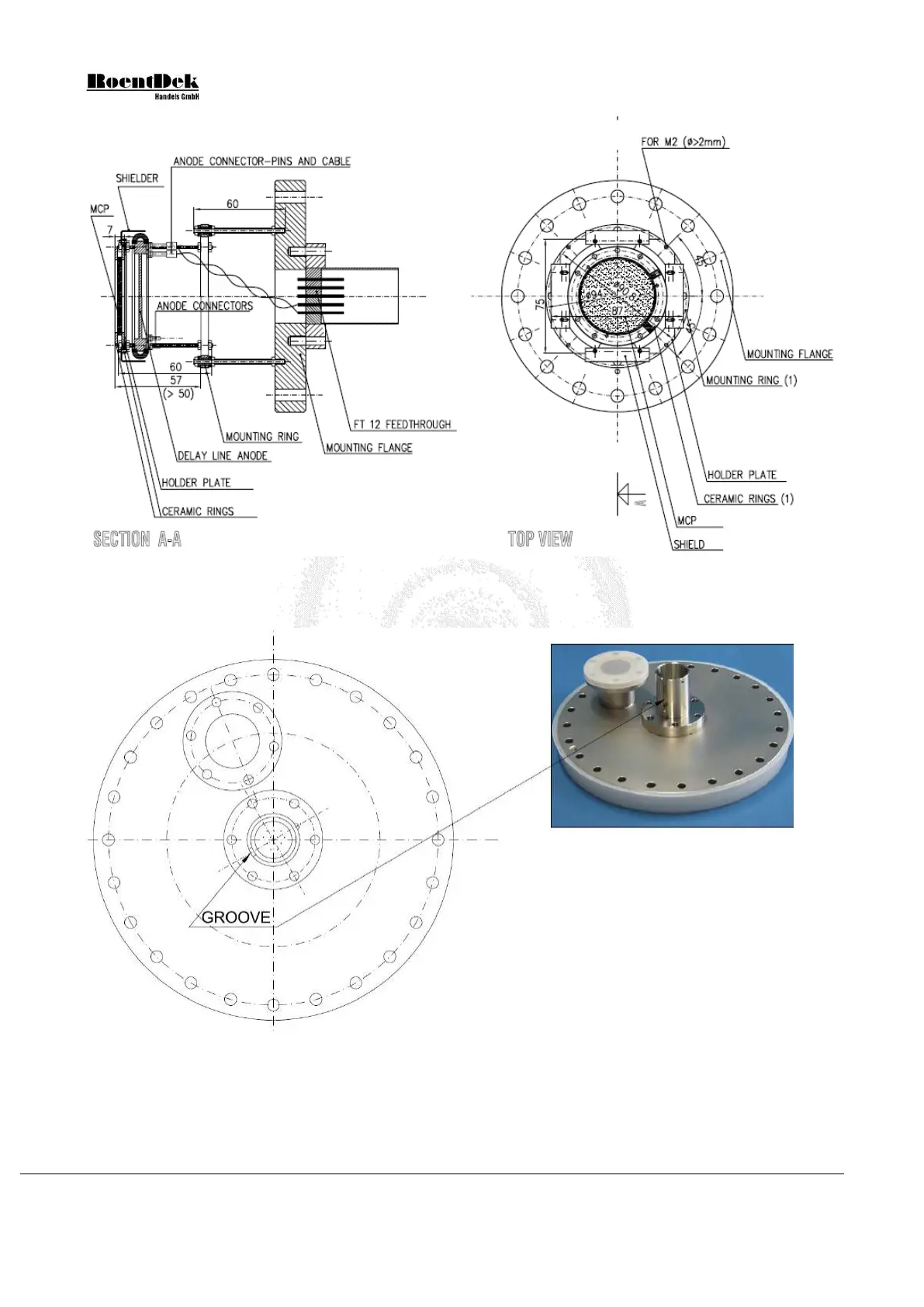
Figure 2.1: Sketch of the detector with mounting flange (only flange mounting option, here: FT12TP/100). For
connecting a Hexanode, the same 12-pin feedthrough is used and an additional set of at least 3 MHV or SHV
feedthroughs (e.g. the FT4) is needed for connecting the MCP front, MCP back, Holder (and optionally a mesh).
Figure 2.2: CF200 flange with two CF35 ports for mounting a Hex80 detector. It is recommended to fix the FT12 12-
pin feedthrough on the center port in an orientation that the groove points perpendicular (or as close to that as
possible) to the direction of the off-center port. This avoids spatial conflicts that can occur for certain item
combination in the FT16TP product package.
Page 24 of 83 MCP Delay Line Detector Manual (11.0.1304.1)