Figure 3.10: Front and rear panel of the ATR19-2 (left) and ATR19-2b (right)
3.7 Final Adjustment for detector operation
The ATR19 units were specifically designed for the read-out of RoentDek delay-line detectors (ATR19-6 for DLD, ATR19-
8 for HEX) and timing detectors (ATR19-2). The ATR19-2 can also be used for the read-out of one delay-line layer.
If the voltages to the detector are supplied in the recommended way the signal from the MCP front or back contact (positive)
has to be connected to ch1- or ch2- and the delay-line signals to ch3+ to ch6+ (or to ch8+). In case of DET40/75 and
ATR19-2: the signal from the MCP front or back contact (positive) has to be connected to ch1- and/or the signal from the
timing anode (negative) has to be connected to ch2.
During the initial start-up procedure and whenever there are doubts about the high voltage robustness of the detector hardware,
only the MCP signal should be connected for verifying the general detector (MCP) function. After an initial start-up procedure
you have verified signals and the noise level from the detector. Assuming all wire connections are correct and all detector
potentials are applied you should see similarly shaped analogue output signals on MCP front/back and the delay-line (monitor
outputs). The outputs from the delay line should have similar signal heights. If not, the amplification factors on the DLATR
boards should be adjusted (see Figure 3.2).
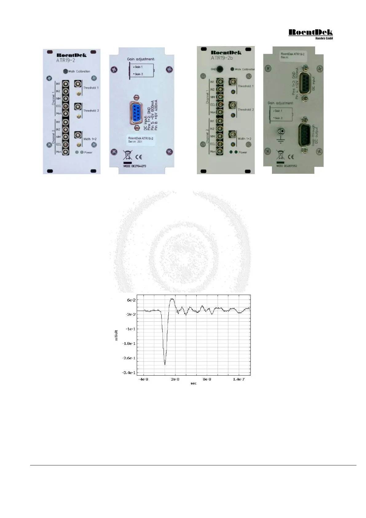
Figure 3.11: Typical amplified pulse shape of the MCP as obtained from the ATR19 analogue monitor output.
The analogue signal height on MCP back or front (channel 1 or 2) linearly corresponds to the charge of the electron cloud
delivered from the MCP for a respective particle. As long as the output pulse height is smaller than 400mV (negative polarity)
the shape of the pulses resembles the input signals that enter the constant fraction stage. For older DLATR boards the analogue
output saturates at this value, however, internally (at the CFD input stage on board) the pulse height can be higher and is still
linear. For normal noise levels below 50mV sufficient imaging results are obtained if the pulse heights distribution has a mean
value of 300mV. The lowest pulse height should still be higher than the noise level. To increase the pulse height one can increase
the MCP bias (not exceeding the maximum recommended value!) or the amplifier gain. If you increase the amplifier gain please
be aware that the noise level will increases proportionally to the amplification factor. The signal-to-noise ratio, limiting detector
MCP Delay Line Detector Manual (11.0.1304.1) Page 43 of 83