Assembly of the MCP-stack
If you have received a DLD120 or HEX120(100) please refer to Chapter 1.2.4.2
1.2.4.1 Assembly of the MCP-stack for the DLD40, DLD80 and HEX80
A cartoon about the assembly of the MCP stack for the DLD40, DLD80 and HEX80 can be found on our web-site in the
MOVIES section. There you can also find cartoons showing the mounting of the MCP stack to the anode.
By now you have to decide if you prefer to solder the cables for the MCP contacts directly to the contact pads on the ceramic
ring, as recommended. Note, that even for UHV environment small amounts of lead-free solder/flux are usually tolerable. All
parts should be cleaned after the soldering.
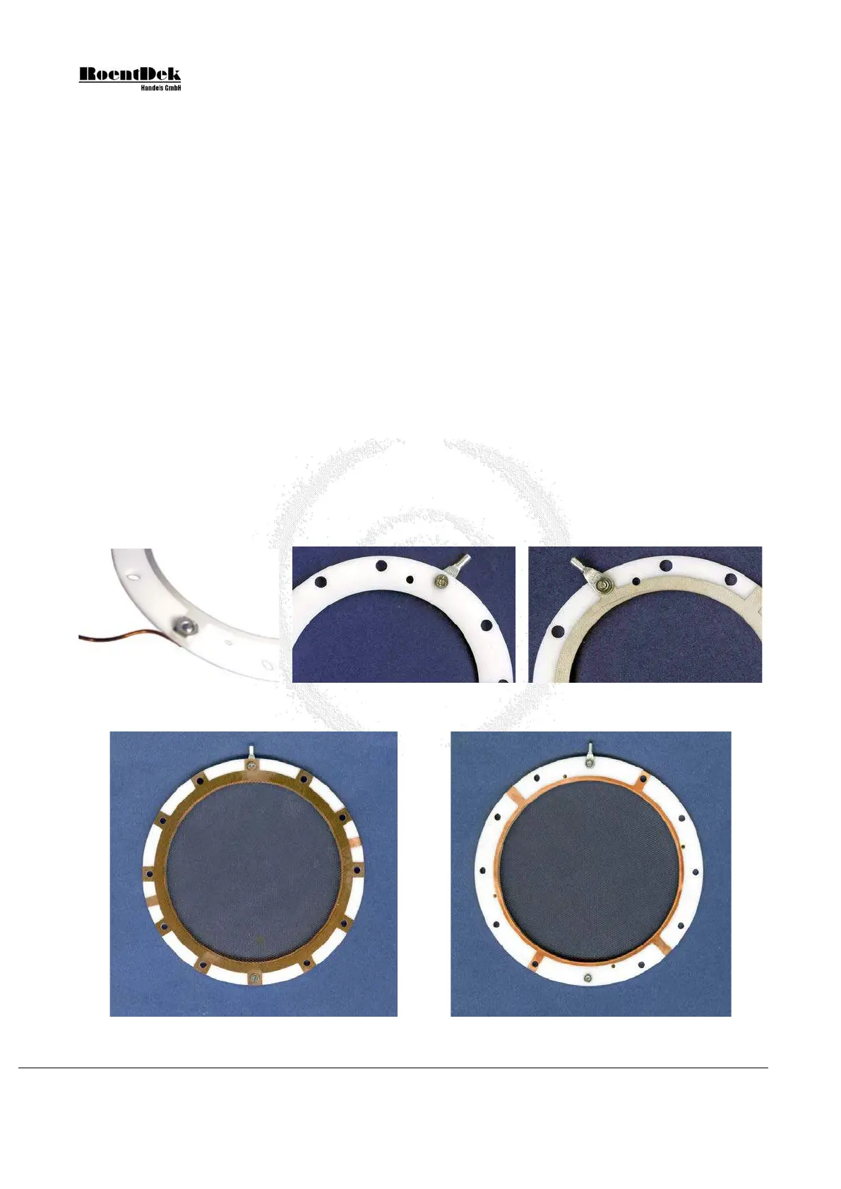
If you prefer not to solder the cables to the ring, fix a cable with the provided M2 screw with the special nut on the front
ceramic ring now. The cable can either be crimped to a contact lug and fixed with a M2 screw or wound around this screw
without using the lug.
If you prefer not to solder the cables directly onto the rings and have received (or prepared your own) connecting lugs and a
screw set fix a cable to the front ceramic ring now. The cable to the feedthrough must first be crimped (or soldered) to the
contact lug with 3mm eye-let and fixed with a special recessed M2 nut and a countersunk M2 screw (4mm long for
DLD80/HEX80 or 3mm long for DLD40), see Figure 1.7.
If you have purchased a mesh from
RoentDek you may mount it now to the front side of the front ceramic ring with the
same (or other) recessed M2 screws/nuts at a desired distance from the front ring. It should be fixed on at least two (for zero
distance) or more positions and must be connected with a bias cable to a feedthrough. If you have purchased any of the
FT12(16)TP products you may connect this bias cable to the “X” line on pin1 of the FT12TP or in case of HEX, to the
vacant MHV/SHV feedthrough on the FT16TP feedthrough assembly (it is then recommended also using a HFST for biasing
the mesh, see Chapter 0
Figure 1.7: Connections to a ceramic ring. Left: cable clamped to a “front” ring (MCP side visible). Middle/right:
cable clamped to a back ring with 3mm lug, countersunk M2 screw and special M2 nut.
Figure 1.8: Free-standing mesh mounted to the MCP front ring (left: front side, right rear side of the front ring).
Page 14 of 83 MCP Delay Line Detector Manual (11.0.1304.1)