even if you have not purchased this option because important features for proper cabling and signal decoupling circuits are
described there.
You need a set of 4 (Hexanode: 6) twisted pair cables to connect the anode wires. In the four (six) corners of the anode’s rear
side each pair must be connected to the wire terminals formed as M2 stubs, preferably with the connector pins provided.
Mounting the cable in a different way (i.e. by M2 nuts) is possible but not recommended, see also Chapter 0. Note that the M2
stubs are not secured against torque. If you have purchased the FT12(16) feedthroughs adequate cables with adequate connector
pins/lugs for both ends are provided with it. Use only so much force that the cables are safely connected and are not moving
when gently wiggling on them. Also connect the anode holder with a cable, wherever suitable (see also below). This cable has
to supply the anode holder potential.
Figure 1.4: Cables for holder and wires on DLD40,
DLD80 and HEX80. The four M2 rods and the MCP
holder plate are on the same “Holder” potential as the
delay-line anode body. The cable can be connected
anywhere on these parts.
Please note that this is NOT the case for the DLD120
and Hex120(100) assemblies where the MCP back
plate is insulated from the Holder and carries the MCP
back potential.
Before connecting the cables to a feedthrough it is important to distinguish the cables that lead to ends of the same single delay
line wire. Both ends must receive the same voltage (U
ref
or U
signal
, see Chapter 2.2).
In order to later obtain an image on the PC monitor according to a phosphor screen (rear) view, the following connection
scheme in the corners is recommended for the DLD detectors.
up left y2 x2 up right
down left x1 y1 down right
Figure 1.5: Orientation of x and y position terminals on anode viewed from the rear side, the outer delay line wires
In this position the sliding shields are recommended to be placed left and right on the (inner) Y-layer side.
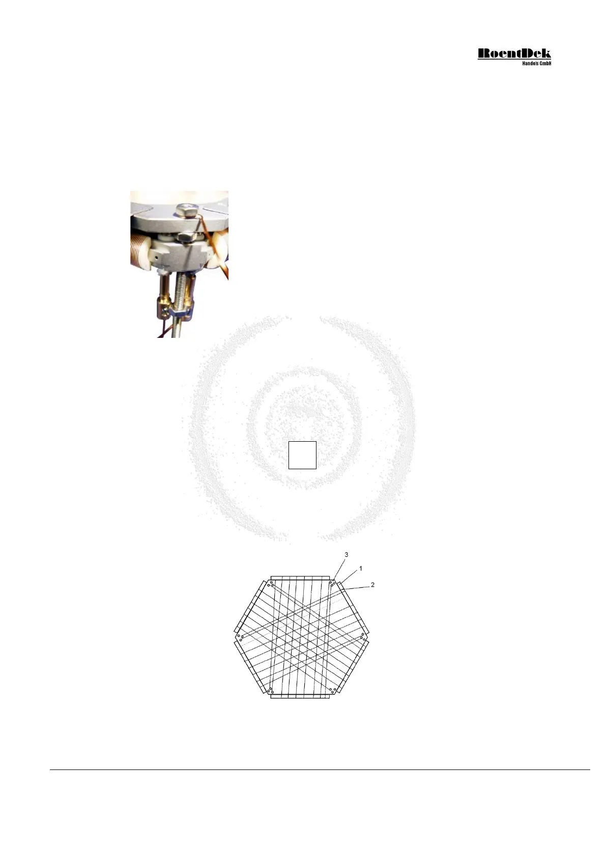
For the Hexanode, the following wiring scheme is mandatory to comply with the position computations in Equation 1.2:
Z2 X2
Y1 Y2
middle outer
layer layer
inner layer
X1 Z1
Figure 1.6: Rear view of a Hexanode with suggested cable connection
MCP Delay Line Detector Manual (11.0.1304.1) Page 13 of 83