Safe and high-performance operation of the detector operation of the RoentDek detectors requires adequate high voltage
supplies and auxiliary passive bias units. In the following the standard units are described. If you have received a different model
please refer to the respective manual.
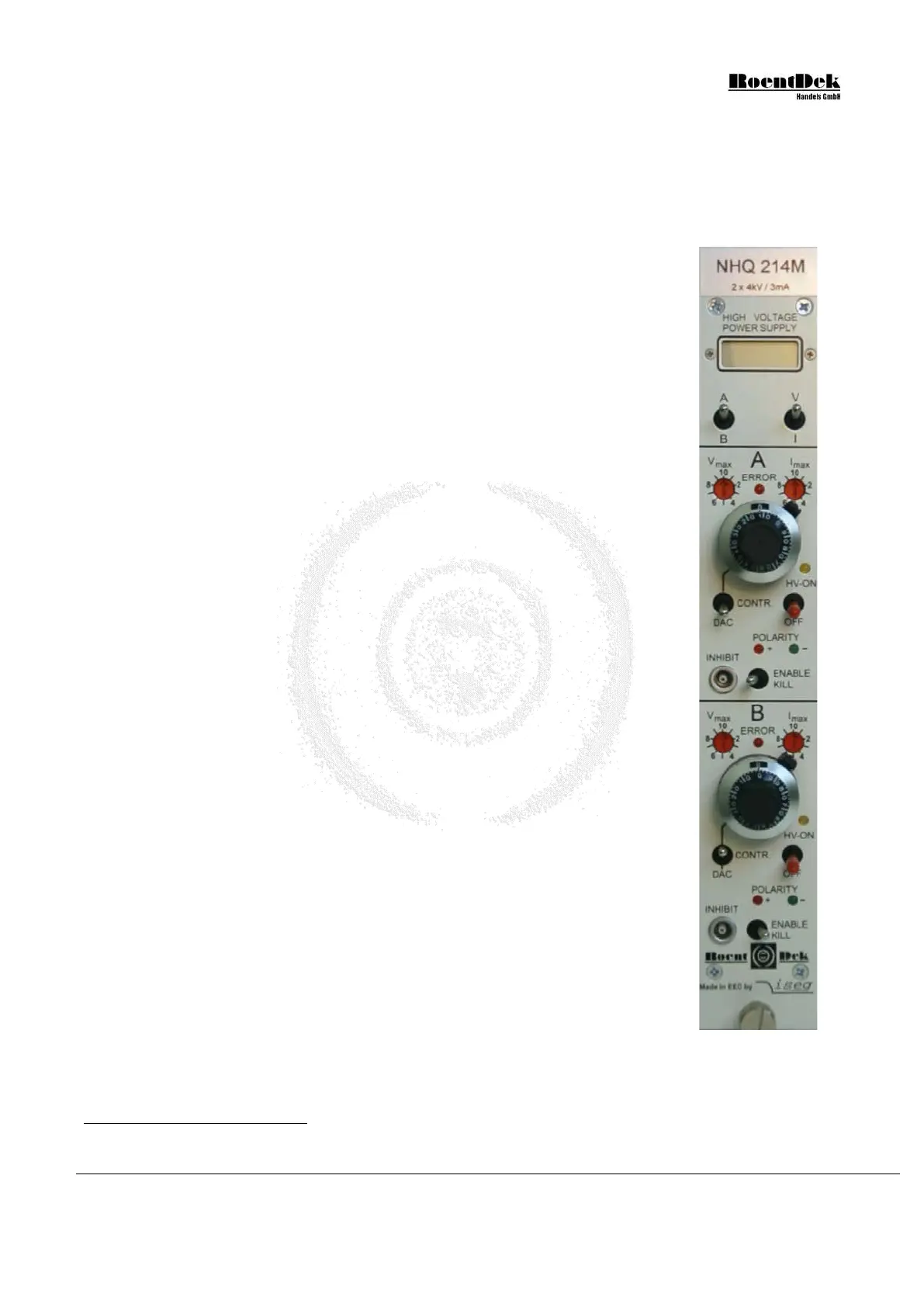
5.1 The HV 2/4 dual High Voltage supply module
RoentDek
2×4kV Power Supply is especially designed for the use of biasing multi-
channel-plate detectors, featuring low-ripple and regulated current limitation and protection. It is
to be powered by a NIM crate
or the RoentDek SPS2 (mini) mains adapter (RoentDek
BIASET3). It is also possible to externally supply the operation voltage using the 9 pin socket
on the rear side panel, supplying the voltages (ripple < NIM-crate standard), according to Table
5.1 (see below). U
e
of ±24V (800mA) and ±6V (100mA) DC have to be provided to power the
module. The “N24” version of the supply requires only the ±24V, see next section.
The switches on the side panel will set the respective channels to negative or positive output
polarity, indicated by an LED on the front panel. Only change polarity when the power is off.
If a channel of the power supply is switched on (indicated by an LED), and the “DAC” switch is
set to upward position, the 10-turn potentiometers at the front panel can be used for manual
voltage setting U
a
(10 turns correspond to 4000V, linear progression). This is the recommended
procedure for operating the
RoentDek detectors.
The voltages can also be ramped externally with an analog voltage input to the Lemo-sockets on
the rear panel (10V analog input corresponds to maximum voltage output, linear progression).
For this the “DAC” switch must be set to “DAC”. Please contact
RoentDek for adequate
remote DC level controls (e.g. the USB-I/O modules).
The A/B switch will set the display to channel A or B, the V/I switch will enable voltage or
current reading of the set channel. The accuracy of the reading is within a few volts and a few µA
(typically 1µA), respectively.
The maximum current delivered is 3mA, the maximum voltage is ±4kV. Both can be restricted
in 10% steps from 0.3mA (or 400V) to 3mA (or4000V) which corresponds to 100%.
*
Usually the current limiter should set to 10%, i.e. 0.3mA when using it with a
RoentDek MCP
detector (exception: biasing via a HVT device).
If the trip protection switch is set to “enable kill” the voltage will be turned off in case of over-
current (e.g. after a spark) or over-voltage (indicated by a flash of the “ERROR” LED), according
to the settings of V
max
and I
max
. In the other switch position the module will try to engage the set
voltage again, however it will trip once more if the limit is reached again and continue this cycle.
This is an unfavorable operation condition if the tripping is caused by detector sparks
and may cause damage.
In case of an error turn down the voltage and turn the module off and/or engage the enable
switch again after verifying a proper state of your hardware. A TTL signal (“high”) on the
“inhibit” input will also deactivate the voltage, like the event of an over-current, according to the
position of the “enable kill” switch.
The hardware ram speed is 500V/sec max. (power switch on/off).
The safest operation mode for MCP is the “enable kill” position. If the current limitation is set low and the switch
is on this position it can happen that an error is indicated when starting to increase the voltage on a certain detector
part, although no problem of the hardware actually exist. This is due to the loading current of capacitors in the
power supply itself or in the signal decoupling circuits. In that case set the switch to the other direction when starting
to increase voltage. You may switch to the “enable kill” position later after the voltage setting is finished.
Figure 5.1: 2x4kV
Power Supply
(front panel)
*
RoentDek can also supply a 6kV and 8kV version (1mA) of this module or modules with even higher voltage ratings. A
“pseudo-floating” power supply is also available. Please refer to the separate manual if you have received such a module.
MCP Delay Line Detector Manual (11.0.1304.1) Page 69 of 83

 Loading...