On the rear panel on some modules you find a 9-pin socket where the external power cable for
the RoentDek amplifier modules of type DLATR6 and ATR19-2 can be powered (only if
labeled accordingly, see
Figure 5.3, not for N24 version. N24 and non-standard modules may not
have this 9-pin socket or the socket is used for digital remote control. Please observe the label on
your specific module).
Warning: the HV output of this power supply can be hazardous if not properly operated.
Never operate the module with open housing.
RoentDek
denies any responsibility for
accidents with their products and is protected by German laws. If you need special
instructions how to handle high voltage power supplies please contact
RoentDek.
Further specifications:
Operation temperature: 0 ... +50°C
Storing temperature* -20 ... +60°C
Ripple (peak-to-peak) < 50mV
Stability ΔU
a
< 2 × 10
-4
or 5 × 10
-5
of ΔU
e
Temperature coefficient < 1 × 10
-4
/
°
C
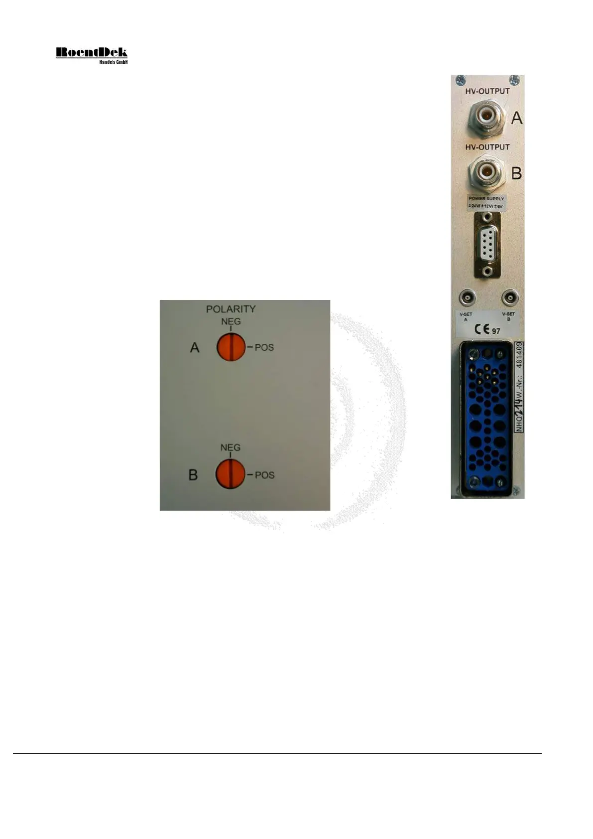
Figure 5.2: 2x4kV Power Supply (side-panel)
Figure 5.3: 2x4kV
Power Supply
(rear-panel)
Changing the Polarity of Channel A and/or B
To change the polarity of either channel, A or B, locate the “red knobs” on the left side-panel (see Figure 5.2
) and place the
module flat on a table showing the side-panel. Gently adjust the slit of the “red knob” to the desired polarity using either an
adequate screwdriver or a coin. Please make sure that the screwdriver is not tilted.
Do not press on the knob! Do not use
force!
The channel is adjusted if you hear and feel the lock in place.
open (reserved for -5.2V on some modules)
Table 5.1: Pin assignments of standard
9-pin sub-D voltage connector.
Page 70 of 83 MCP Delay Line Detector Manual (11.0.1304.1)