Figure 1.18: Assembly of MCP-stack - Stage 4 (DLD40 & DLD80)
Check with an Ohm meter that there is no electric contact between “MCP back”, “MCP front” and “holder” plate. There
should be a resistance in the 10-100MΩ regime between “MCP back” and “MCP front”. In the presence of humidity the MCP
stack resistance may be less than the default value.
For disassembly reverse all steps.
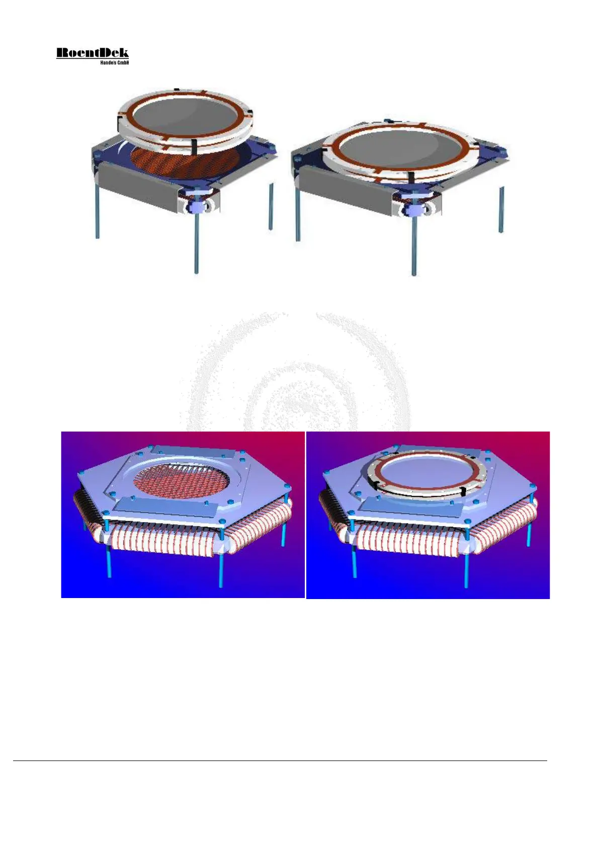
For the HEX80, the same butterfly-shaped MCP holder plate as for the DLD80 is used. Additionally, a hexagonally-shaped
intermediate plate connects the standard DLD80 holder with the Hexanode. The shields are replaced by a pair of metal sheets
that hold the MCP stack in position.
Figure 1.19: Hexanode with holder
Figure 1.20: Hexanode with mounted MCP-Stack
1.2.4.2 Assembly of the MCP-stack for the DLD120 and HEX120
A cartoon about the mounting of the MCP stack for the DLD120 and HEX120(100) can be found on our web-site in the
MOVIES section. There you can also find cartoons showing the mounting of the MCP stack to the anode.
For the 120mm MCP size (or 100mm) the mounting is different than for the 40 or 80mm MCP sizes, no ceramic rings are
used. Instead, the MCPs are fitted between a metal square-shaped rear plate which mates to the delay-anode and a metal front
ring. The rear plate and the front ring have an indention for the MCP on one side. The MCP stack is fixed by 6 special M3
screws make from PEEK which is an insulating UHV-compatible polyimide material.
Only on older systems M2 rods from the same material are also used to fix the MCP stack to the anode.
Page 18 of 83 MCP Delay Line Detector Manual (11.0.1304.1)